Post by sadface on Feb 29, 2020 21:50:11 GMT 12
G'day Guys,
May I introduce my next experiment: The 12VAC aikido.
Essentially the 12vac goes through a voltage sextupler to make a reasonably high B+ from a low voltage transformer. The heaters are pulled off the centre of the sextupler and wired in series.
12vac becomes a b+ 94vdc. They can be used with a 12vac transformer and 6DJ8 tubes or an 18VAC transformer and 12AU7 tubes. 18VAC becomes a B+ of 148vdc.
It's quite an elegant solution in its simplicity. Not so high performance as independently regulated B+ and heater supplies for each channel like on my "big" Aikido preamp but a much smaller footprint and a single $30 toroidal transformer instead multiples. Perfect for trying to stuff into a chassis where space is at a premium.
I ordered a pair of these beautiful boards a while back, 1 for a friend and one because I was already paying shipping from 'Murica'. One was in kit form for 6DJ8 tubes, however this idea fell through.
I was intending to use 6N1P tubes which are sold as a drop in 6DJ8 replacement. However, I have come to believe that the curves are a bit different and the actual drop in replacement is the 6N23P which is not nearly so cheap and plentiful.
Thus the plan changed and now I will build the 18VAC version and use 12AU7s. There are good NOS CV4003 tubes available from TWL123 on trademe for a relative steal compared to importing 6DJ8s.
I've got some of these CV4003 tubes in my mono blocks and they were quite an improvement on the New production Tungsol 12AU7s that were previously in there. No auctions listed today but I've emailed Tom before and he has good stock so availability should be good for the time being.
The longer term plan here to is couple one of these boards with a pair of Rod Elliot P3A boards and a pair of beefy power supplies to make an integrated amp for a friend. Short term plan is to get one up and running on the test rig for proof of concept and too see how it sounds.
I will be interested to see how this compares in sound the "The backup" as the ultimately have a similar cost. Circa $150 for The Backup and Circa $200 for the Aikido including tubes, boards and shipping.
I placed a parts order from Mouser on Friday which should arrive on Tuesday according to DHL. I must say I have been amazed at how good DHL are for shipping. DHL can get me PCBs from Shenzhen and Mouser parts from Dallas faster than NZ couriers can reliably get my packages to customers one suburb over in Auckland. Auckland to Tokoroa is reliably overnight but if we want to send orders to customers from Glenfield to Milford I will often get an angry phone call from the customer half a week later. I also love the DHL track and trace system which shows each step in the logistics chain for piece of mind that things are moving. I can see my mouser order has already moved from Dallas to Cincinnati.
Time allowing I might have test rig up within a week or so.
|
Post by colinf on Mar 1, 2020 21:17:46 GMT 12
That’s quite low HT voltage, hopefully the triodes are set at low current so that they’re still operating linearly. Looks good though!
AMR-iFi R&D
|
Post by sadface on Mar 4, 2020 17:01:24 GMT 12
Damn I love Mouser,
I ordered 9:30pm on Friday.
The goods arrived 3pm Tuesday afternoon from Dallas Texas.
The parts order I made with Element 14 has partially arrived with 2/3 yet to be sent. Credit where credit is due though. The goods did arrived 9:30am on Tuesday after being dispatched from Sydney on Monday afternoon.
DHL and Toll are bloody great.
|
Post by colinf on Mar 6, 2020 19:51:32 GMT 12
Toll used to annoy me as if I wasn’t in they would deliver to the depot 20km away, necessitating a trip into town. The other couriers would just leave it in a safe place at home. Mouser are great, they have all sorts of stuff and swift delivery. But you need to order over £33 to qualify for free shipping. I think in NZ it’s $66.
AMR-iFi R&D
|
Post by sadface on Mar 25, 2020 7:37:14 GMT 12
G'day folks,
I imagine there will be a bit more activity around here over the next few weeks of increased hobby time. I made a trip to jaycar yesterday to grab some extra heat sinks, speaker binding posts and wiring.
I've started on the 12vac aikido board. Resistors are in place.
My ocd levels increase with each build. Is making sure all the writing on resistors is face up and in the same direction going to far?
Diodes and caps to go and then I can whack it on the test rig and start tuning the heater voltage.
One quirk with these boards is that the heater voltage is a function of the B+ voltage. Thus one has to tune the heater voltage using R15 as a dropping resistor.
I will have to build the amp and put in some tubes I don't value too much. Then I need to check that there is 48v across all 4 series wired heaters. Too much and R14 needs to go up in value, too low and it needs to go down.
At this stage I will leave the zeners off as they seem to have been problematic for other builders. I saw one gentlemen who was having issues with R15 becoming a lighbulb with the zeners installed.
I have some used new production tung sols that should work nicely for testing.
All things going to plan there might be a fresh noise making device for noise testing this evening.
|
Post by sadface on Mar 25, 2020 9:19:42 GMT 12
Hello again,
I've made good, rapid progress this morning.
Sockets, caps and diodes are now installed.
The sockets are some decent feeling ceramic ones that came from Glassware audio.
Resistors are all Vishay Dale RN60/65.
Film caps are Wima MKP4.
Coupling caps are Cornell Dubilier 940C types. I've read great things about these being fantastic bang for buck. Still $10 a piece but if one believes the internet; every bit as good as Audiophile grade Polypropylene caps with gold font, fancy names and high prices. We'll see.
Electro caps are Rubycon and Nippon Chemicon: 10000 hour types. Diodes are all genuine On Semi MUR410g
I generally like to avoid using stupidly expensive parts. I like to stick to high quality name brand types from reputable suppliers. I did once fork out for some Mundorf silver/oil caps at horrendous cost.
Testing time!
I will chuck it into my open top testing chassis so this shouldn't take too long before it either makes acrid smoke or sweet sweet noise.
|
Post by sadface on Mar 27, 2020 8:12:49 GMT 12
Good Morning folks,
A productive day yesterday.
Everything has been wired up in the test rig. No smoke or explosions which is always nice on first start up. Initial testing has been passed.
I'm bang on the 120v expected after the B+ dropping resistor R12.
The heater supply however is currently too low: 43.9V across all 4 series wound heaters. I need to change the heater dropping resistor R15. I went with the highest value for the first run. 47R which is dropping 6.75V. I need 50.4V for the heater so I suspect I want to use no resistor at all as 43.9 + 6.75 = 50.65V. I will replace the 47R resistor with a 10R and see how things look. I am expecting to simply use a jumper wire in this position but we'll see what 10R looks does first.
Curiously I noticed no light from the heaters on the tubes. I am assuming this is due to being under volted at the heater by 1.5V.
|
Post by Owen Y on Mar 27, 2020 10:10:05 GMT 12
I generally like to avoid using stupidly expensive parts. I like to stick to high quality name brand types from reputable suppliers. Me too, I like to get a cct up & running & see if it is worth it first, before contemplating better parts. Curiously I noticed no light from the heaters on the tubes. I am assuming this is due to being under volted at the heater by 1.5V. Sometimes this happens, I think in some tubes, the heater can be less or more visible, due to the heater cathode tube or plate construction. Heater voltages are generally specified to an acceptable tolerance of +/- 10%. That's a wide tolerance of 11.3 - 13.9v (for 12.6v heater config). But on the lower side is generally better for tube longevity. But I wouldn't fret too much, esp if the supply varies with mains voltage.
|
Post by sadface on Mar 27, 2020 11:08:46 GMT 12
This morning I replaced the Heater dropping resistor R15
I changed from 47R to 1.5R. 
Now the heater voltage is too high at 51.5V
I remembered to take some extra measurements this time. Raw heater voltage before R15 is 51.8V
Across each rectifier I get 25.9V from a Raw ac of 20.6V measured at the board. The heater comes off D3 and D4 which 2x 25.9v = 51.8V so its nice that matches up.
Working backwards from 51.8V I need to drop 1.4V to make 50.4V. Heater current is 150mA therefore R=E/I = 1.4v/0.15A = 9.33ohms.
I could have saved myself some soldering if I had taken some extra measurements and done the maths before swapping in the 1.5R resistor.
So now I know I should have used the default 10R resistor in this place. That's what I get for reading horror stories on the internet instead of simply doing maths and measurements.
I am currently waiting for all the caps to discharge so that I can make what is hopefully the last mods before noise testing.
Meanwhile.....
I have been doing some blacksmithing for another project.
I've taken a U shapped peice of mild steel that made up the chassis for a sony midi system I've been salvaging.
I've hammered it into a 'flat' sheet using an old BMW straight 6 engine block as an anvil and a claw hammer.
A bit more hammering and I got rid of the dimples and annoying flanges etc.
A cordless jigsaw was used to cut out a section. By no means is this elegant or pretty. But a fun experiment in salvaging metal for chassis.
The purpose for this is to box in the front of another chassis I salvaged from a digitech integrated amp. It had only plastic on the front but I want everything completed sealed in metal for RF/magnetic shielding purposes. 
I'm going to make a small integrated amplifier using the Mark II backup preamp boards (the ones with coupling caps and no RF filter) and the spare pair if gainclone boards I have lying around.
I will clad the front, top and sides with some nice looking plywood once all is done. Plenty of time for such projects now so no reason why not.
This will be my first experiment in salvaging components to decrease build costs of an AMP. I got the digitech amp on Trademe for $20. I have salvaged the transformer which seems to be something like a 250VA type. I reckon between the transformer and chassis I've probably saved myself at least $100.
|
Post by sadface on Mar 27, 2020 14:24:02 GMT 12
Alright!
I replaced R15 with a 10R 3W resistor
The heater is now measuring 50.8v which is close enough for now. I'm over-volting each heater by 0.1V however I don't think this will make a significant difference to tube life. More significant for this would be fast rise on the B+.....
We are now at the burn in stage.
I will leave it running for the evening on the old boombox prototype for the rest of the day (it's quite handy having a device that doesn't matter if it gets damaged).
Tomorrow I will chuck it into the main system for noise sampling.
|
Post by sadface on Mar 28, 2020 9:35:31 GMT 12
G'day Gents,
After a bit of burn in last night, the test rig is now in my main system for the first round of listening tests. I'm currently using an old tube set: 4x new production tung sol 12au7 that all have a year or 2 use in them as the driver and phase inverter in my KT88 monoblocks. I only have 1 matched quad of CV4003 tubes in stock which I would prefer to save for the monos so I might have to wait until post lockdown to install a new tube set.
I see Tom has set the auction for a 1month end date.....
So far the sound is quite different to the solid state backup. I was expecting warmer tones however it is possibly the opposite, it is perhaps slightly brighter above the mid range. The bass is every so slightly rolled off compared to the Backup - still plenty deep however I think I am missing 1hz or so. I use Skream's remix of LaRoux- going in for the kill, as my bass test. With a good preamp I can rattle the house however there the bottom end just feels the smallest bit rolled off and lacking of that gut feel. This should be perfectly acceptable as I intend to make one of these for a friend who doesn't have a sub-woofer good for 20hz so I doubt they will notice the absense.
I might well change out the 1uF coupling cap for something like 2.2uF after the lockdown when I can maybe get such things.
On the other hand, the sound immediately gained that 'holographic' character that just seems a bit more real.
Individual voices and instruments seem to have a bit more 'space' or 'air' around them.
Harmonies are just a bit easier to pick out. I guess I could say that everything just sounds a bit more real.
I'm going to say that the sound is pretty phenomenal for an ancient used tube set in a barely burnt in amplifier.
|
Post by Owen Y on Mar 28, 2020 10:54:08 GMT 12
The bass is every so slightly rolled off compared to the Backup - still plenty deep however I think I am missing 1hz or so. Looking v good. The Aikido, as I recall, is a pretty neutral, low distortion design - although there seem to be many versions. Bass - I always look at the PSU first. Check that the RC filter 'cells' throughout go way down low in freq to Gnd. eg. Morgan Jones suggests a f(-3dB) point of 3Hz if you want flat response up at 20Hz. This includes also (& maybe most importantly) the last 'decoupling' RC cell feeding the tubes - R12-C2 & R12-C11. Another area to check, is the output coupling RC network, forming a high-pass - ie. C3 & R7 in parallel with the input load R of the following amp, possibly 47k or 100k.
|
Post by sadface on Mar 29, 2020 9:42:57 GMT 12
G'day chaps,
A bit of progress on my amateur blacksmithing project.
I've managed to get the front panel something close to square and true.
Once everything is torqued down it holds something like a rectangle shape, close enough for my purpose.
Getting good quality right angles has been a bit difficult with the tools/knowledge at hand. I think I need something like a small square of steel to get up under the flanges to hammer them square.
The joys of Covid-19 lockdown. What would normally be a trip to Bunnings to find something suitable becomes a case of 'what do I have on hand that might work'
I've managed to improvise a dimple die tool using a socket, a high tensile M6 bolt, some large flat washers and my cordless impact wrench. 
I destroyed 4 bolts, 2 nuts and 3 washers in the process.
The last bolt lasted just long enough to create the dimple before the thread was stripped and then I managed to strip the hex pattern on the outside of the nut. It took a while to drill out the head of the high tensile bolt but I got it out eventually.
I will probably end up putting some rivet nuts on the flanges of the front panel so that there is something decent to bolt into.
I am still getting my head around how I am going to attach the wood to the metal and how to allow disassembly, my current thinking is: option 1) use wood screws front the inside and then allow holes for chassis bolts.
Option 2) replace all the current bolt mounts with something like m4 rivnuts and attach the wood from the outside by bolting the wood down to the new chassis hardpoints.
|
Post by sadface on Apr 30, 2020 10:57:20 GMT 12
Hi Owen,
I finally took the couple of minutes to look at the filters in the PSU
C2 is parallel with C11 so I am forgetting about the 0.1uF here.
With R12 as 2k and C11 as 220uF. I calculate a low pass filter with a corner frequency of 0.361 Hz.
I also looked at the filter on the output.
With C3 set to 1 uF, R7 set to 1M and a 25k input impedance for the load. I calculate the corner frequency at 6.5Hz.
I think this might explain the slight roll off at the very bottom.
If I was to change c3 to 2.2uF I calculate a corner at 2.96HZ which sounds a bit better.
|
Post by sadface on Jun 11, 2022 21:58:24 GMT 12
G'day Guys,
Now that my gainclone is finished I'm going back to this project.
I'm going to house it in a more appropriate chassis.
I will also use this as an opportunity to test a relay input selector that I designed a few years back.

All soldered up ready to go for testing.

As is this simple PSU board.
|
Post by RdM on Jun 16, 2022 19:18:07 GMT 12
That's very fine work! 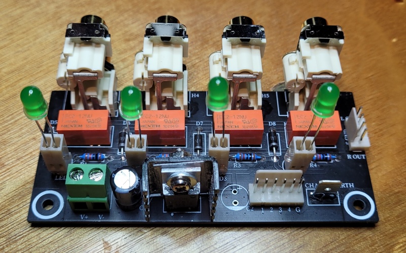  But what happens if some idiot ignorant or unknowing person or twerp takes out an led, twirls it around, and replaces it?
Maybe some markings or other id for anode cathode?
Praising with just one tiny faint damn ;- ?
What fantastic skills and beautiful work on those pcbs.
I only recently started playing with veroboard.
That was fun too, at least 3 revisions clearing out mistakes.
Great learning experience, still awaiting a first live test of the result.
Oh, for the current mirror for the Wurlitzer jukebox valve amp.
Cheers!!
|
Post by sadface on Jun 25, 2022 10:00:28 GMT 12
This LED arrangement is simply for testing purposes.
Assuming it all works as intended, I will run them on wires to the front panel of the chassis to indicate which source is in use.
Thankfully you can still see the silkscreen for the LEDS so its easy to see which way around the flat side of the LED goes, which is good because I am prone to acts of the dumb.....
|
Post by sadface on Jun 30, 2022 22:03:19 GMT 12
G'day Guys,
I got around to rigging up a test rig this evening.
Mixed results so far.
Nothing exploded which is a fantastic start.
The relays all trigger properly.
The selection works properly.
The indicator LEDs do not light up.....
Next step is look over the schematics and boards and see if there's any obvious mistakes to be found.
If nothing can be found there I will have to look at the dropping resistors in series with the LEDS, perhaps they are running at too low a current to light.
|
Post by sadface on Jul 2, 2022 21:00:28 GMT 12
I can't find any errors on the pcb or on the schematics. I think it is an issue of current. I=E/R =10/10000 =0.001A
1mA is would be perfect for a high brightness type, however the LEDS i've installed here these
typical forward current of 20mA suggests I need to give these a bit more juice.
I will get some higher brightness types to test.
|
Post by colinf on Jul 3, 2022 0:41:39 GMT 12
LEDs are connected reverse polarity in the schematic above. 1mA is fine for high brightness leds but normal ones need a bit more current.
AMR-iFi R&D
|
Post by sadface on Jul 3, 2022 21:59:04 GMT 12
Good spotting Colin, I don't know how I missed that.
A fix was very easy.
I simply twisted the leads on the LEDs around 180 degrees and popped them back into the housings.
Voila, properly polarised LEDs that light up as they should.
1mA is also perfect as I only want to use these for indication purposes, not to light up the room.
Test rig on the kitchen bench, far right LED shining.
Far left LED shining.
I double checked all the continuities while I was there. The RCA inputs all match up nicely with the output when powered.
Job done. Testing complete.
Next step is to replace the 1uF coupling caps currently on the Aikido board with some Epcos 2.2uF PP caps that arrived last week.
After that I will need to test the whole rig again with the new power transformer.
I wanted to power both the amp and the input selector off of a single power transformer. Due to costs and availability I ended up with a 2x18v 100VA transformer. I will need to check all the voltages with the new transformer which is suspect will exhibit less sag that the current 30VA transformer. I may need to adjust R15 to keep the heaters happy.
|
Post by sadface on Jul 4, 2022 20:29:52 GMT 12
I had half an hour tonight so progress was made.
I got the Aikido board out of the old test chassis and replaced the old coupling caps with the new ones.
Next up is rigging up a test rig with the new power transformer.
|
Post by RdM on Jul 4, 2022 21:19:55 GMT 12
I had half an hour tonight so progress was made.
I got the Aikido board out of the old test chassis and replaced the old coupling caps with the new ones.
Next up is rigging up a test rig with the new power transformer.
I see that's out of stock now.
But I have so many HT and even separate heater transformers, and chokes, that I'd go for an externally powered one.
Or, I mean, integrated with a power amplifier on the same chassis (maybe valve - I have also have output transformers.).
I have quite a few 6SN7s and also noval types. So your mono boards are appealing too.
Just in mind of liking and wanting to build a future valve amp or two too, and looking at what chassis I have stashed as well.
Might well take months!
Cheers!!!
|
Post by sadface on Jul 8, 2022 22:17:11 GMT 12
G'day Guys,
Some good progress over this week. I only get a bit of time each evening.
I've dressed all the wires on the new power transformer for testing over the last couple of nights ready for testing this evening.
Testing reveals that I will need to do a bit more work.
The voltages are all up a little bit as expected when changing from a 30VA transformer to a 100VA.
B+ is 124v after R12
The Heater voltage is 51.4v across the 4 series heaters or 12.85v each.
Time allowing I will run some extra measurements tomorrow night.
We'll see if measurement confirms what I would expect from ohms law. E=IR = 0.15Ax10R = 1.5V 51.4v + 1.5v = 52.9v is what I would expect to see before R15.
52.9v - 50.4v = 2.5v to drop.
R= E/I = 2.5v/0.15A = 16.67R
We'll see if my maths matches the Fluke.
I think I have a 3w 20R resistor lying around in my stash.
That would be a 3v drop instead of 2.5v Which would give 12.475v on each heater.
I guess the question is firstly whether 12.85v is unacceptably high in the first place to warrant further surgery on the pcb. Secondly, assuming I did want to do surgery: whether its worth ordering in a 16R resistor rather than just using a 20R from my stash or running with a slightly under volted heater.
|
Post by colinf on Jul 9, 2022 19:29:11 GMT 12
The higher the heater voltage, the less long term life it generally will have. For 9 pin tubes I usually use 6.05 to 6.1v per 6.3v-rated indirectly heated cathode. So the 20 ohm resistor would most likely be ok.
AMR-iFi R&D
|
Post by RdM on Jul 9, 2022 20:25:09 GMT 12
G'day Guys,
52.9v - 50.4v = 2.5v to drop.
R= E/I = 2.5v/0.15A = 16.67R
We'll see if my maths matches the Fluke.
I think I have a 3w 20R resistor lying around in my stash.
That would be a 3v drop instead of 2.5v Which would give 12.475v on each heater.
I guess the question is firstly whether 12.85v is unacceptably high in the first place to warrant further surgery on the pcb. Secondly, assuming I did want to do surgery: whether its worth ordering in a 16R resistor rather than just using a 20R from my stash or running with a slightly under volted heater.
Wouldn't that imply only 0.375W dissipation? (Maybe my math is wrong too!;-?)
Jaycar even has both 5W wire wound & 1W carbon film of 15 & 18 ohm.
I've often taken my meter in to select to better than 1% over the bell curve for what I wanted, especially for matched pairs. And have found "+-5%" indeed all that way, so you might be able to select what you want. Yes the staff didn't mind me crouched down selecting resistor values.
Asking first or not. But not all carbon film resistor packs are easily open to probe. It's good to see the variation though, imho.
I forget now whether heaters were rated at +-5 or 10%, but surely likely at or slightly below spec is or was better? (an easy look up, but why not get it as close as possible to optimal?)
Clumsy post. I'll try to do better next time! ;=}).
Can you mount the heater voltage adjustment resistor outboard, avoiding altering the pcb tracks?
Just thoughts on the fly;- I might be wrong! ;=})
Edit: Maybe lower voltage is better than higher, but you could use parallel resistors to get it right?
Of course you know all this! ;=})
|
Post by sadface on Jul 12, 2022 21:46:55 GMT 12
G'day Guys,
I've been measuring my mains voltage over the last couple of days to get a feel for how the heater voltage relates to the mains.
Last night at 8pm the mains was 224Vac, unfortunately I didnt think to measure the heaters at the time but I suspect they would have been slightly low.
At 10pm last night the mains was 233 and the heaters were 51.6v
At 6:30am this morning the mains was 236, the heaters were 51.6v
At 7:40pm this evening the mains was 230, the heaters were 50.4v
At 8:30pm this evening the mains was 231.5, the heaters were 50.6v
I am thinking from this that the heaters are not getting significant over voltage under normal circumstances. 50.4v is my target and at 230v mains, the heaters run bang on 50.4v
I think when I did the measurements the other day it was at something like 9:30pm when the mains seems to be a bit higher.
I am still considering increasing R15 slightly for the sake of biasing things towards a slight under voltage in normal conditions. Such that when the mains is up the heaters are still closer to spec.
|
Post by sadface on Jul 19, 2022 21:41:58 GMT 12
G'day Guys,
I decided to not change the dropping resistor for the heaters. It all seems to be on target so I won't trouble myself with it any further.
With that decision out of the way I can move on to implementing a new home.
Here's a draft layout in an old Yamaha chassis.

Power supply on the left hand side (viewed from the front) as seems to be the convention amongst the commercial manufacturers. I'm using this as a size template as I think its about the right size.
I was going to actually use this chassis but it would be quite the pain to work around with its various holes/projections etc. So this time, I'm going to start from scratch instead.
I'm working on a different chassis concept this time. It involves a cheap sheet metal bender I purchased recently.
All going to plan, this will work out a fair bit cheaper than my last build for a higher quality finish. If successful, this will then set the template for a few more builds to follow.
|
Post by colinf on Jul 20, 2022 18:58:38 GMT 12
A few manufacturers seem to have adopted the power supply on the left of the chassis. That would make it easier to avoid induced hum into the circuitry on the right, from components stacked on top of each other if the transformers are all on the same side.
AMR-iFi R&D
|
Post by sadface on Aug 14, 2022 22:03:05 GMT 12
G'day Guys,
Progress is progressing.
I organised some steel. 1.2mm electro-galv steel sheet for the sides and 2mm for the top and bottom.
I got me a new ryobi cut off tool.
Today I was allowed some time away from toddler duties to do some cuts. 2x 140x250 for the sides.
|


