Post by sadface on Jun 5, 2023 21:25:38 GMT 12
Thanks!
Sadly I don't have anything that can measure capacitance very accurately.
I have a DMM that can measure down to 0.01uF.
|
Post by sadface on Jun 7, 2023 20:45:48 GMT 12
G'day Guys,
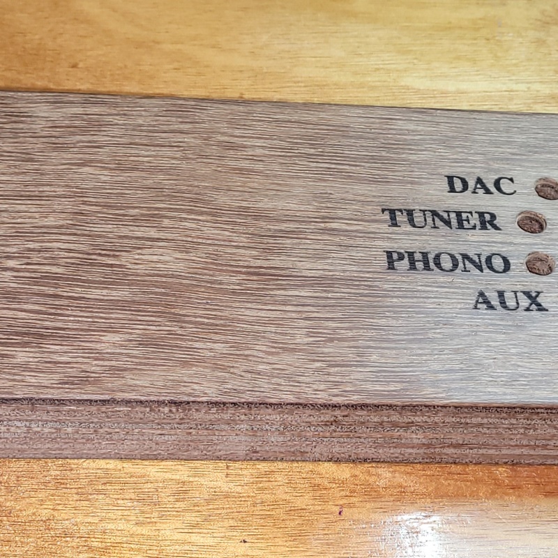
The front panel came back from laser engraving today!
I'll give it a light sand with some 240 grit and then start slathering on the danish oil.
|
Post by RdM on Jun 8, 2023 20:49:38 GMT 12
G'day Guys, The front panel came back from laser engraving today! [...] I'll give it a light sand with some 240 grit and then start slathering on the danish oil. I'd go on with 400 after 240, on dry wood, with a nice flat sanding block or machine. If on varnish polyurethane or paint builds, I'd use wet, 400 600 800, etc.
You can buy cheap packs 2 ea of the range wet&dry easily.
Achieving a hard wearing matte satin or gloss best finish might need polyurethane or even fancy marine products, dilute first coat etc. But these are just off the cuff comments, I'm no expert! ;=}) Sanding it smooth certainly helps a lot in my limited experience, though.
Of course on coarse dry wood, using it dry, you have to vacuum away dust to see where it's at. But I'm sure you know that! ;=})
I'd wondered though after seeing your photos - how deep does the laser burn go, i.e. how deeply could you sand it? 1mm? Etc.
Cheers !
[Edit: Was there a 320 in between? Anyway progressive sanding might make for a nicer finish, even or especially if using oil. Research... ]
|
Post by sadface on Jun 10, 2023 20:09:56 GMT 12
The lasering isn't too deep, 1mm at most.
I don't normally go above 240 grit on wood, call me lazy perhaps.
I did the hard work sanding already before it was lasered.
I gave it a quick lick with some 1200grit that was the first thing I found.
I slathered on a few coats of Brixwax Danish oil today.https://www.bunnings.co.nz/briwax-500ml-danish-oil_p0316969
I love this stuff. It smells like mineral oil and beeswax. Much nicer than all the other more chemically smelling stuff like Cabots.
Tomorrow I will give it another sand to flatten out and raised grain and slather on a few more coats of Danish oil.
|
Post by RdM on Jun 11, 2023 19:34:10 GMT 12
Thanks for the tip re Danish oil.
I have 3 old wooden dining chairs that I'd saved with intent of restoring.
I've got (ex TM) some nice fabric for the seats, foam etc,
They'll need a clean first, and then I was wondering whether to sand and apply a new finish.
So old, maybe they had French Polish. Two oak, one maybe rimu but I'm not sure.
With all the corners and struts of the frames sanding clean would be a lot of work.
But it's a great tip for future amplifier building with wood sides &or fronts.
|
Post by sadface on Jun 11, 2023 20:11:07 GMT 12
Here's the results from the first day of Danish Oil.
This photo was taken first thing this morning before anything was done. You can see the little bits of blue lint stuck in there from the rag I used yesterday to apply the oil. I gave it a light sand with some 240grit sand paper before continuing to slather on some more Danish Oil.
Last night I also made some good progress on the wiring.
The ground wiring is all sorted.
This box is made from multiple parts bolted together. Rather than relying on the bolts to properly connect each segment, I am running ground wires to each panel to make sure everything is grounded properly.
All that remains now for wiring is the output wiring and the indicator LED wiring.
|
Post by RdM on Jun 11, 2023 23:10:15 GMT 12
[ ... ] Last night I also made some good progress on the wiring.
The ground wiring is all sorted.
This box is made from multiple parts bolted together. Rather than relying on the bolts to properly connect each segment, I am running ground wires to each panel to make sure everything is grounded properly.
Hmm, no pun intended even if maybe so... Is there not a poddibility (I liked the adjacent key typo so much I left it in) ~ that that then creates ground loops? I've mentioned a similar thing in the chassis of the Wurlitzer valve amplifier I was working on, and may be again.
That's from the '60s, but isn't there a thing about separating the audio ground from the chassis and main audio ground now?
Maybe Colin F can comment.
I admit to some confusion and ignorance wrt grounding too, even though I've bookmarked read and downloaded a lot. And have old books.
The separation with say a 10 ohm resistor. etc. The old Wurlitzer has extra wires around the chassis to components, but I haven't fired it up yet.
Presumably insulated RCA input sockets from the chassis, going to the PCB, and the whole chassis becomes a ground plane shield apart from the pcb.
I'd have thought bare new metal machine screws to chassis parts would make contact enough. Do or would extra bolts washers & wires really improve it?
But I'm just curious ; ~
Perhaps test first, without speculating if extra grounding might be needed? You want or need some sort of baseline test, surely. Else how would you know?
Just thinking aloud! ;=})
Best regards; ~ RdM
|
Pundit

Post by papahemi on Jun 12, 2023 16:12:28 GMT 12
[ ... ] Last night I also made some good progress on the wiring.
The ground wiring is all sorted.
This box is made from multiple parts bolted together. Rather than relying on the bolts to properly connect each segment, I am running ground wires to each panel to make sure everything is grounded properly.
Hmm, no pun intended even if maybe so... Is there not a poddibility (I liked the adjacent key typo so much I left it in) ~ that that then creates ground loops? I've mentioned a similar thing in the chassis of the Wurlitzer valve amplifier I was working on, and may be again.
That's from the '60s, but isn't there a thing about separating the audio ground from the chassis and main audio ground now?
Maybe Colin F can comment.
I admit to some confusion and ignorance wrt grounding too, even though I've bookmarked read and downloaded a lot. And have old books.
The separation with say a 10 ohm resistor. etc. The old Wurlitzer has extra wires around the chassis to components, but I haven't fired it up yet.
Presumably insulated RCA input sockets from the chassis, going to the PCB, and the whole chassis becomes a ground plane shield apart from the pcb.
I'd have thought bare new metal machine screws to chassis parts would make contact enough. Do or would extra bolts washers & wires really improve it?
But I'm just curious ; ~
Perhaps test first, without speculating if extra grounding might be needed? You want or need some sort of baseline test, surely. Else how would you know?
Just thinking aloud! ;=})
Best regards; ~ RdM
... also interested
We are what we pretend to be, so we must be careful about what we pretend to be.
|
Post by Citroen on Jun 12, 2023 19:50:28 GMT 12
Ditto
|
Post by RdM on Jun 12, 2023 20:14:15 GMT 12
On reflection perhaps extra wire connections between steel chassis mounted and contacted components, as in the Wurlitzer amp, are merely in parallel with the ground plane chassis, and provide better conductivity. Not like a ground loop between devices or within one. But I'm sure I'd think the steel compartments would be sufficiently in contact. So mains ground to chassis, then audio input earths insulated from the chassis go to the board, and its earth/ground system, and there's a single connection from that pcb & etc. audio ground to the chassis, whether via a 10 ohm resistor or not, yes?
|
Post by sadface on Jun 12, 2023 21:04:43 GMT 12
On reflection perhaps extra wire connections between steel chassis mounted and contacted components, as in the Wurlitzer amp, are merely in parallel with the ground plane chassis, and provide better conductivity. Not like a ground loop between devices or within one. But I'm sure I'd think the steel compartments would be sufficiently in contact. So mains ground to chassis, then audio input earths insulated from the chassis go to the board, and its earth/ground system, and there's a single connection from that pcb & etc. audio ground to the chassis, whether via a 10 ohm resistor or not, yes? I was thinking about your earlier post this morning and I agree with your later post.
I think it would be in parallel if the chassis was completed grounded without the wire. I think it should all be at the same potential.
I have not yet had to implement a ground lift. So far everything I have built has been hum free without the need. I may be necessary later, we'll see!
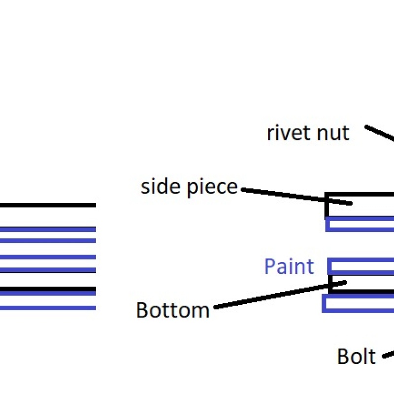
I think this image illustrates the issue as to why I think it is required.
The left side shows the situation without the ground wire.
The paint between the layers would insulate one bit of steel from the other. The bolt will have continuity with the thread in the rivet nut, but without make sure there is a connection between the bolt and the bottom plate it is quite plausible to have the bottom plate floating. The right side is what I am thinking of: star washers to bite through the paint and make sure there is continuity.
I might be going over the top here but I do like safety.
|
Post by RdM on Jun 12, 2023 21:48:48 GMT 12
On reflection perhaps extra wire connections between steel chassis mounted and contacted components, as in the Wurlitzer amp, are merely in parallel with the ground plane chassis, and provide better conductivity. Not like a ground loop between devices or within one. But I'm sure I'd think the steel compartments would be sufficiently in contact. So mains ground to chassis, then audio input earths insulated from the chassis go to the board, and its earth/ground system, and there's a single connection from that pcb & etc. audio ground to the chassis, whether via a 10 ohm resistor or not, yes? I was thinking about your earlier post this morning and I agree with your later post.
I think it would be in parallel if the chassis was completed grounded without the wire. I think it should all be at the same potential.
[ ... ]
The paint between the layers would insulate one bit of steel from the other. The bolt will have continuity with the thread in the rivet nut, but without make sure there is a connection between the bolt and the bottom plate it is quite plausible to have the bottom plate floating. The right side is what I am thinking of: star washers to bite through the paint and make sure there is continuity.
I might be going over the top here but I do like safety.
Ah I forgot about the paint. Yes, old texts talk about the importance of grinding off paint on a chassis where you're going to make a ground connection, with star washer to bite in, & etc.
Thanks for the quick response ;-
|
Post by sadface on Jun 20, 2023 20:51:30 GMT 12
I'm still working away.
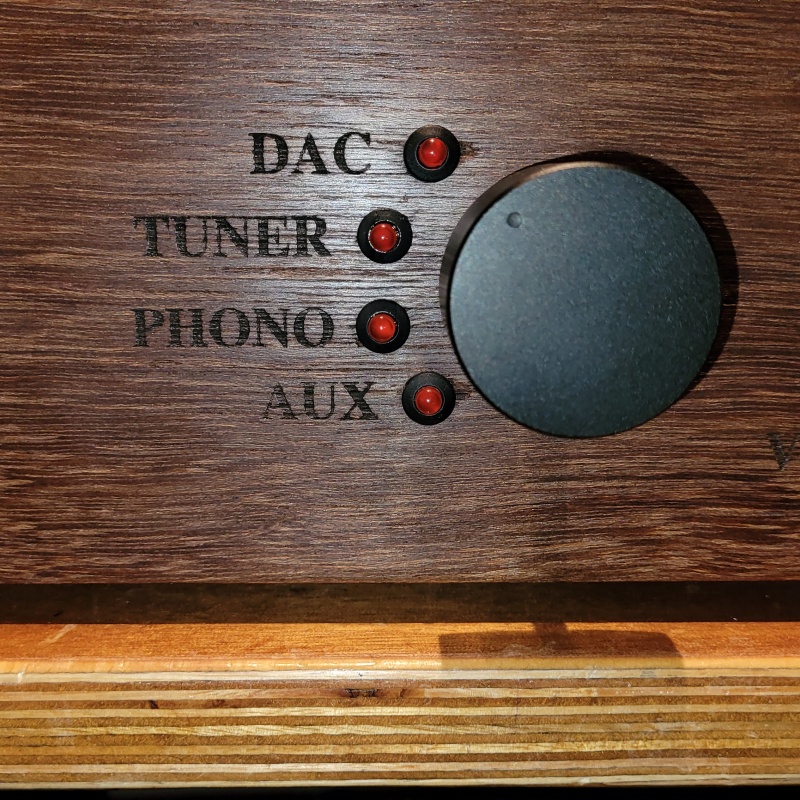
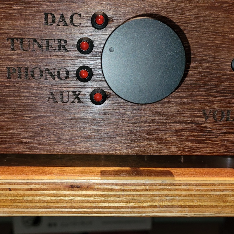
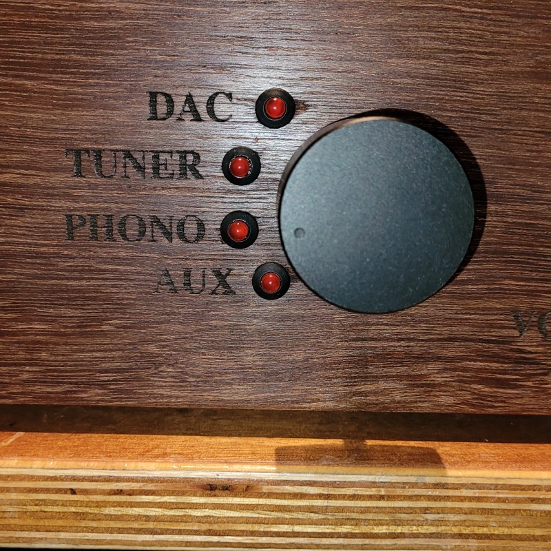
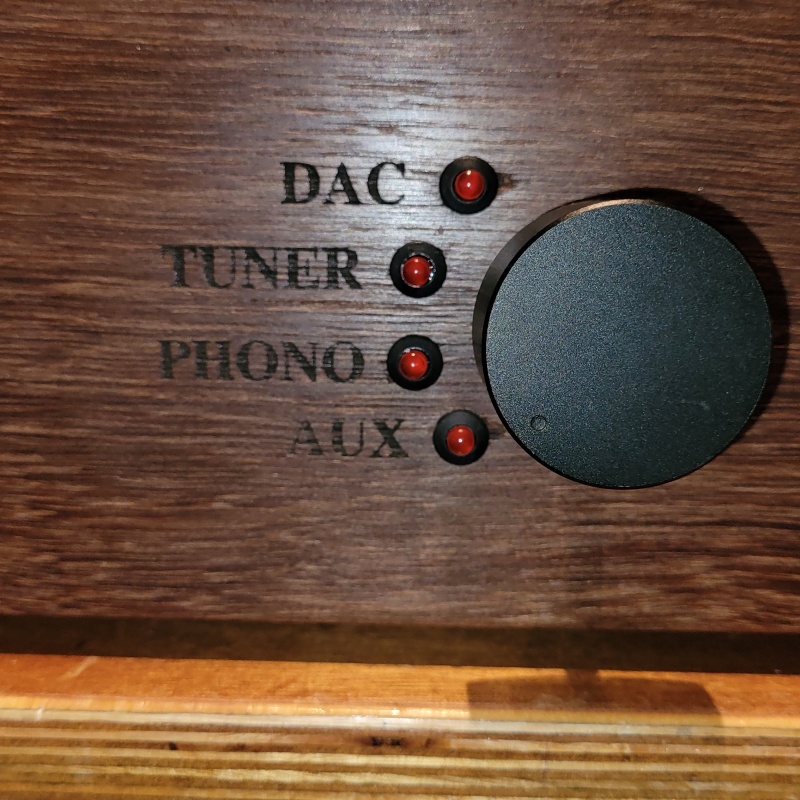
The front panel is looking good. I still need to do some more finish work but its good enough for some fitment testing. The LED clips weren't amazing in function. I couldn't actually get the leds to clip into the clips but a little dab of super glue fixed that problem. The look is exactly what I was looking for.
I tested the throw on the source selector switch last night. It works beautifully.
There's a bit of paralax on the photos as the shaft hasn't been cut down yet meaning the knob is an inch or 2 away from the front panel.
It took a bit of work to get everything lined up nicely on the 15° throw angle on the alps switch. I think it turned out beautifully and was worth the effort.
And here we are with the wiring for the indicator leds on the front panel. This is the general idea of how the runs will work.
A bit of testing to make sure I have the right wires going to the right places and I will terminate the wires and then move on to what should be some of the final steps.
I am in two minds regarding the output wiring: I rather want to only do it once since with the twisting of the pair it is a pain in the backside to separate the pair of wires and the rca socket from its ground lug once its all soldered on, heatshrunk, braid wrapped etc.
So, I either have to whip up some quick and dirty output wiring so that I can do a final test before paint. Then do the wiring properly for final assembly.
Or, work on the basis that everything worked properly before and therefore should work perfectly again and simply proceed straight to paint and final assembly.
|
Post by colinf on Jun 23, 2023 21:53:36 GMT 12
Nice. I’d hook it up temporarily to check it’s all working first.
AMR-iFi R&D
|
Post by sadface on Jul 5, 2023 21:41:08 GMT 12
I decided to go with the wise course and do a test run before final assembly.
Here's the draft assembly. Not all perfect but good enough for testing.
I took it to work and put it on the PAT: test tag passed.
And here's it on the testing amp.
The first round of tests was passed this evening. No blown fuses. The input selector leds all light up in order. No annoying clicks or pops changing inputs. No humming or buzzing. Appropriate music like noises coming through the speakers.
Tomorrow I should have time to plug it into my main system and make sure there's no issues and then its time for disassembly and painting.
|
Post by sadface on Jul 7, 2023 22:32:09 GMT 12
And now its all in pieces again!
Last night I threw the preamp into my main rig. No dramas at all.
The main thing I wanted to test in the main rig was that their was no funny interactions with the dual mono power amp.
Thankfully, there wasn't. No hum, no drama.
So tonight I took the hour the take the whole thing apart. Put all the bits in a box and tomorrow I will start on painting the chassis.
There is 3 other jobs to be done before final assembly:
1) Do the proper final output wiring.
2) Cut the shafts down for input and volume controls.
3) Punch the copper sheet to be riveted to the back for the power information: 230v 50hz etc.
Ideally I will have this all done before next Sunday when a friend of mine is up from Christchurch for dinner and some listening while he's in town.
|
Post by RdM on Jul 7, 2023 22:46:19 GMT 12
And now its all in pieces again! Last night I threw the preamp into my main rig. No dramas at all. The main thing I wanted to test in the main rig was that their was no funny interactions with the dual mono power amp. Thankfully, there wasn't. No hum, no drama. So tonight I took the hour the take the whole thing apart. Put all the bits in a box and tomorrow I will start on painting the chassis. There is 3 other jobs to be done before final assembly: 1) Do the proper final output wiring. 2) Cut the shafts down for input and volume controls. 3) Punch the copper sheet to be riveted to the back for the power information: 230v 50hz etc. Ideally I will have this all done before next Sunday when a friend of mine is up from Christchurch for dinner and some listening while he's in town.
Well, good luck and happy times to complete, best wishes, & etc,
|
Post by colinf on Jul 8, 2023 18:09:14 GMT 12
Good the testing was successful!
AMR-iFi R&D
|
Post by sadface on Jul 17, 2023 22:35:52 GMT 12
Not far to go on this build.
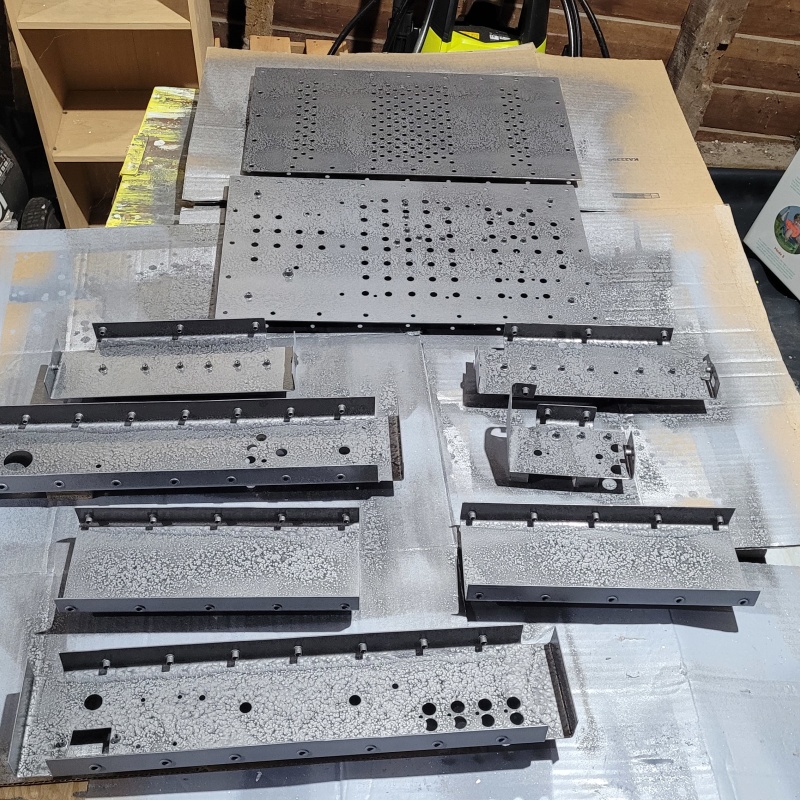
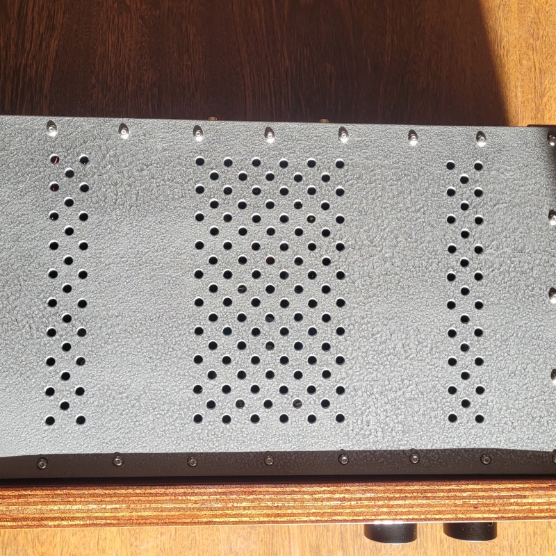
Painting is all done.
First side painted.
Reassembly is finished except for one issue with the source selector switch.
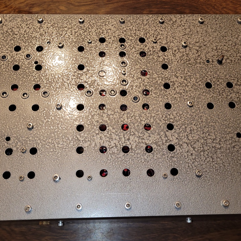
A good shot of the hammered finish, I love this stuff.
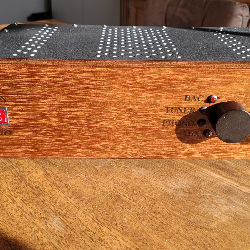
Front shot.
Many fasteners!
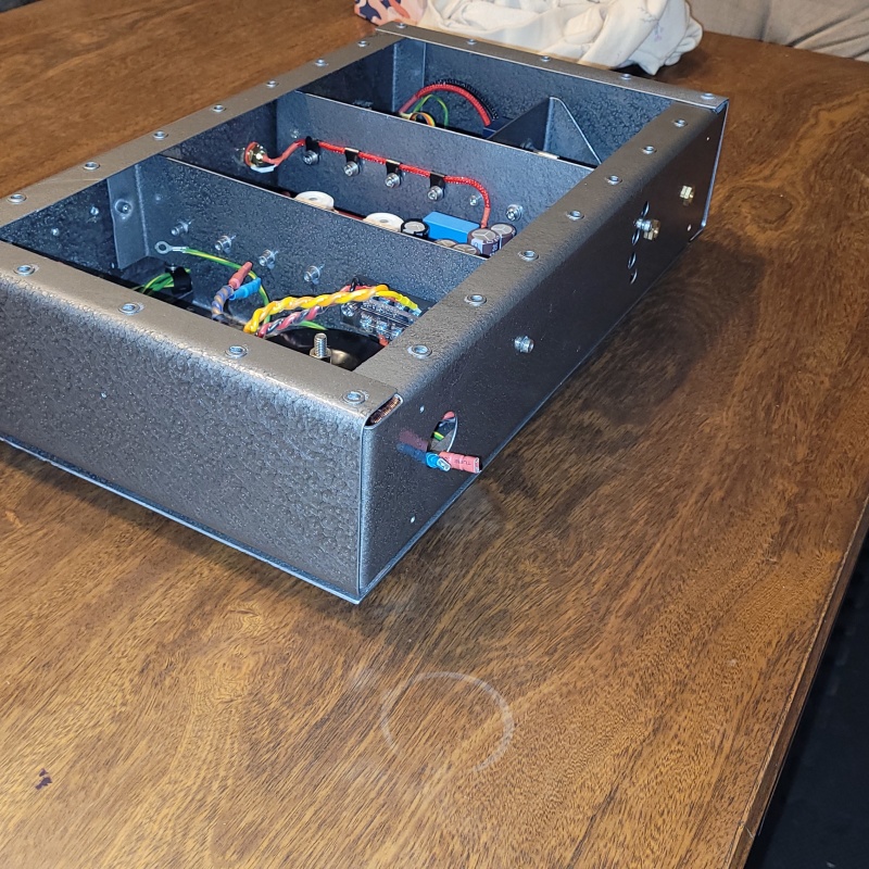
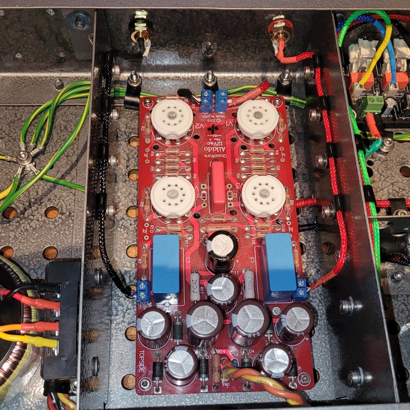
Finished wiring minus the source selector.
Here's how the ground wiring ended up. There is one loose wire ready to attach to the top plate. I've checked everything with the multimeter and every bolt has continuity back to the earth so that worked out well. It might have been unnecessary, some strategically placed star washers was probably sufficient but extra safety is never a bad thing.
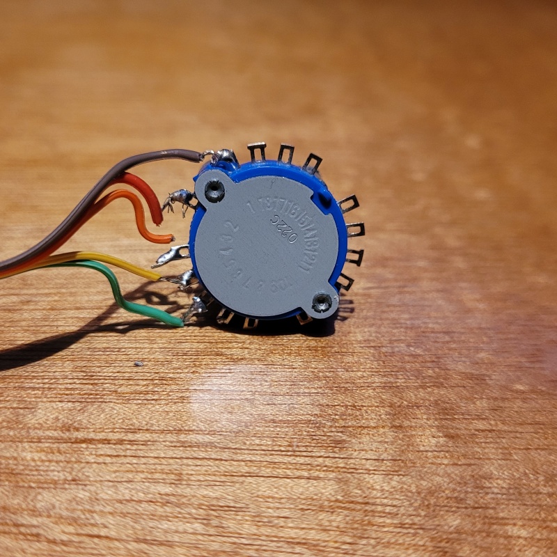
A small issue arose with the source selector switch. Somewhere along the way, one of the wires fatigued off the lug.
This was soldered up with some cheap ribbon cable a year ago for experimentation and is clearly not up to proper standard.
I will take the chance to replace the ribbon cable with something a bit more durable and tidy it all up to match the wire colour coding I used for the leds.
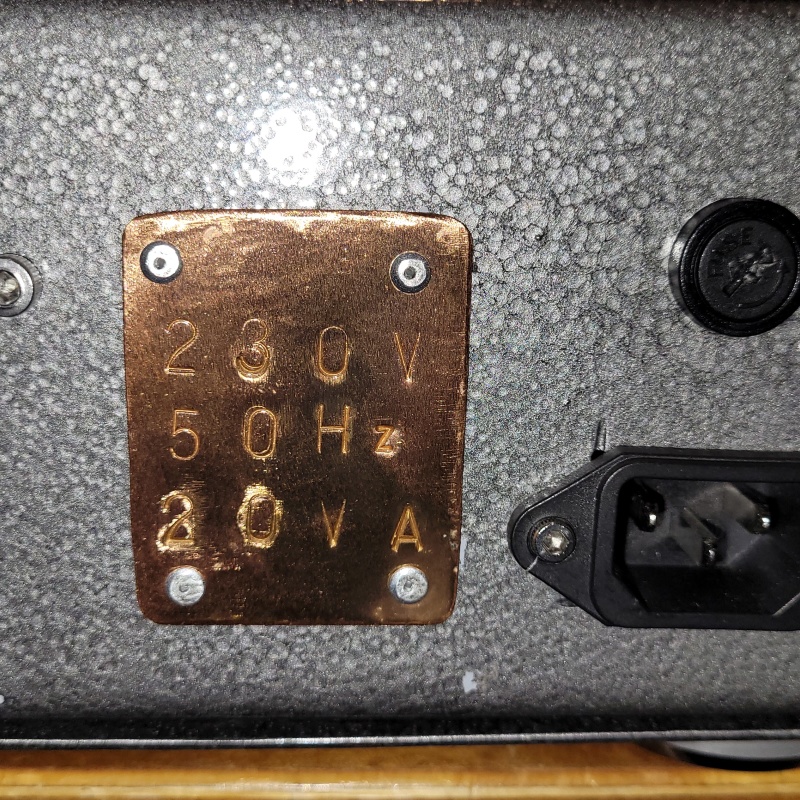
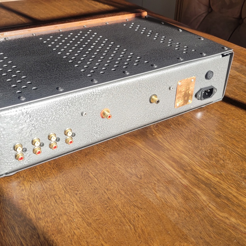
I took the chance to play with the letter punch set again. I wanted the mains power information to be very durable as this kind of thing sometimes rubs off etc. A bit of copper sheet with a quick clear coat to keep it from oxidising. Not quite as prettily done as I would like but perfectly serviceable. I think I will use this further for rear panel labeling in future builds. I didn't allow any rivet holes to use it further in this build.
The back panel will be the last part of the build. My wife is going to print me out the labeling for the ins/outs and the fuse spec on clear vinyl. I've got a spare piece of metal I painted to experiment with to see how the vinyl performs.
|
Post by colinf on Jul 18, 2023 6:35:58 GMT 12
The Hammerite looks great. Love the copper transformer rating plate. Safety with electrical contact between the painted chassis parts is good!
AMR-iFi R&D
|
Post by sadface on Jul 22, 2023 21:53:35 GMT 12
G'day Guys,
The build is all done. I will take it into work and give it a quick test on the PAT before I power it up but assuming it works as it should it is done!
3/4 shot.
Top shot.
Front Shot.
Side shot
3/4 rear before labeling.
The back panel after labeling. My wife whipped up the labels on clear vinyl.
Its taken a little over a year since I decided this preamp was too good for the open test chassis it was in. Its been a good journey. Some good experiments and lessons.
Bring on the next build!
|
Member

Post by snewt on Jul 22, 2023 23:24:14 GMT 12
Well done sadface! I've really enjoyed following your build. I hope it brings you many hours of listening pleasure.
|
Post by colinf on Jul 23, 2023 4:53:05 GMT 12
Well done! Power switch….up is on?
AMR-iFi R&D
|
Pundit
Post by papahemi on Jul 23, 2023 17:22:33 GMT 12
So good to get stuff finished and playing, you may have written about it earlier but I don't recall or see a phono ground?
We are what we pretend to be, so we must be careful about what we pretend to be.
|
Post by RdM on Jul 23, 2023 19:46:55 GMT 12
So good to get stuff finished and playing, you may have written about it earlier but I don't recall or see a phono ground?
My impression was that there is no internal phono stage, so the phono RCA sockets would merely receive from an external phono preamp, no earth ground lug needed.
Hopefully there will be no hum if when one is connected!
|
Post by RdM on Jul 23, 2023 19:51:56 GMT 12
Well done! Power switch….up is on? Evidently... I find I'm indifferent nowadays, ages ago NZ (&UK?) convention was on down, US the reverse as I recall. But my bedside lamp is on up, and odd other pieces of gear... I suppose perhaps which ever way to switch fast might have been considered?
A downward stroke faster than an upward one? It might be interesting to delve into the history of up & down switch on-off conventions...
|
Pundit
Post by peter0c on Jul 24, 2023 10:05:13 GMT 12
It is pretty obvious really. If you accidentally knock a switch it is likely to be a downward stroke. It is harder to accidentally knock upwards so the US standard 'up for on' is safer.
|
Post by sadface on Jul 24, 2023 15:35:19 GMT 12
No internal phono stage, it was simply a logical label to me when I was thinking what I might actually plug into to preamp.
In Duncan's brain, everything has a separate box anyway, notice it is DAC rather than cd etc
Tuner - surely a separate box
phono - one day I will make a phono stage.....
Regarding the power switch:
Up as on was what I found when I did a small survey of power switches on devices.
|