Post by sadface on Mar 23, 2023 19:27:03 GMT 12
I've got a good deburring tool. I just love using cordless power tools. Any excuse! I recently upgraded from an angle grinder to a cordless power file. So my more recent work is a bit less rough. www.bunnings.co.nz/ryobi-18v-one-power-file-skin-only_p0099292The step drill bit can leave quite a bit of 'push through' on the opposite side of the drill hole. Especially on larger holes. Often 2mm or so. I have tried using my deburring tool but I've found a quick lick with the angle grinder or the power file and a quick tap with the step drill bit gives really nice clean holes. I will be tidying up all the grinding marks once I'm done with all the metal working. Hopefully soon: A few holes in the back and front panels and a lot of holes in the top and bottom and then its onto wood working and test assembly.
I'm at the part of the build where I get really excited because the end is in sight. I've cleared most of the hurdles that keep me up at night and I'm almost at the extra fun bit: Wiring!
|
Post by RdM on Mar 23, 2023 20:29:05 GMT 12
Thanks for the quick reply and great update!
Power file? It looks more like a miniature belt sander? What's the grit?
Yay, wiring! ;-)
|
Post by sadface on Mar 23, 2023 20:48:12 GMT 12
Yeah it is a mini belt sander basically. Cordless which it very easy to use. And 'fairly quiet' so I can use it in the basement while the toddler is asleep. At least compared to the angle grinder which would be very impolite to use outside of daytime. There are of course cheaper corded options but I am a sucker for anything cordless. www.bunnings.co.nz/ozito-260w-file-sander-fsr-3000_p629062013 x 455 belt. Comes in 40,80 and 120 grit belts from bunnings. I've seen up to 240 grit on Ali express. So far I've only used the 40 grit belts for deburring and rounding off the edges on some Rimu shelves being constructed for Wifey. Once I get to finishing this project I will pull out the finer grit belts. Finishing, painting and wiring/assembly are some of the most fun. Although all of it is fun really. The 183 vent holes in the top plate are some what daunting, however if I take my time and be sure to enjoy the process it won't take too long. Pending some bits from Ali Express, I should have the metal work done in the next few weeks. Wood Work might take me a few weeks as I have some experiments to conduct on some off cuts before I attempt the one chance to get it perfect front panel work around LEDS and labeling. I have considered getting the labeling work done by laser however I'm going to go for that old school letter punch look. I like the aesthetic and also for the sake of doing everything myself. I've come so far there's no point cheating just before the finish.
|
Post by RdM on Mar 24, 2023 19:20:12 GMT 12
[ ... ] Wood Work might take me a few weeks as I have some experiments to conduct on some off cuts before I attempt the one chance to get it perfect front panel work around LEDS and labeling. I have considered getting the labeling work done by laser however I'm going to go for that old school letter punch look. I like the aesthetic and also for the sake of doing everything myself. I've come so far there's no point cheating just before the finish.
My Dad had a metal letter punch set;- I've had a wooden handle lino cutting set punched with surname for ~ 60yrs.
But other DIY audio folk have faced the same problem and come up with a variety of solutions. Have a look.
I quite like the laser printer transfer method, like for pcbs, which would work on wood if smooth enough, protective lacquer or spray varnish afterward.
|
Post by RdM on Mar 24, 2023 21:00:13 GMT 12
While metal letter and number punches might suit the brutalist heroic epic construction, gee, you'd want to line them up accurately, perhaps on a clamped horizontal steel rule, then judge spacing and kerning by eye ... I thought that Letraset and similar transfers were hard enough to line up in my experience. I'd kind of deplored Ecofan's early hand engraved lettering, even though it's not that bad, and despite how historic it now is. That amp uses push-pull parallel EL95 as outputs;- I've collected a few mostly NOS while it's been sitting on the shelf.
|
Post by sadface on Mar 25, 2023 21:05:27 GMT 12
Love that engraving. So crude and so wonderful for it.
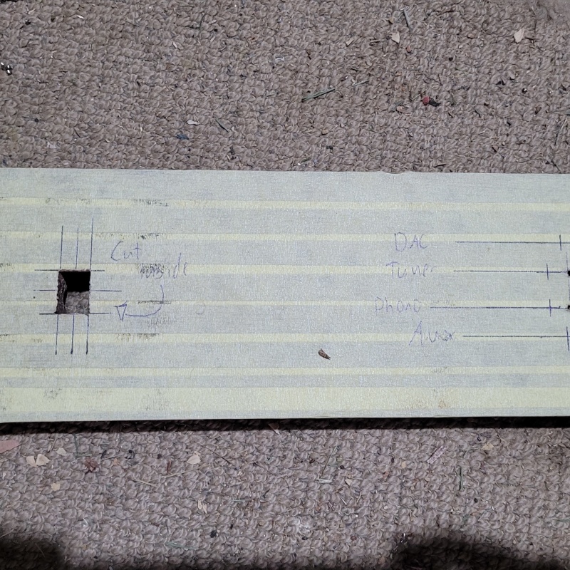
I had some good progress today. I had an hour this morning and a bit more time this afternoon. Power switch socket was drilled / cut / filed / chiseled.
Power switch all nicely fitting
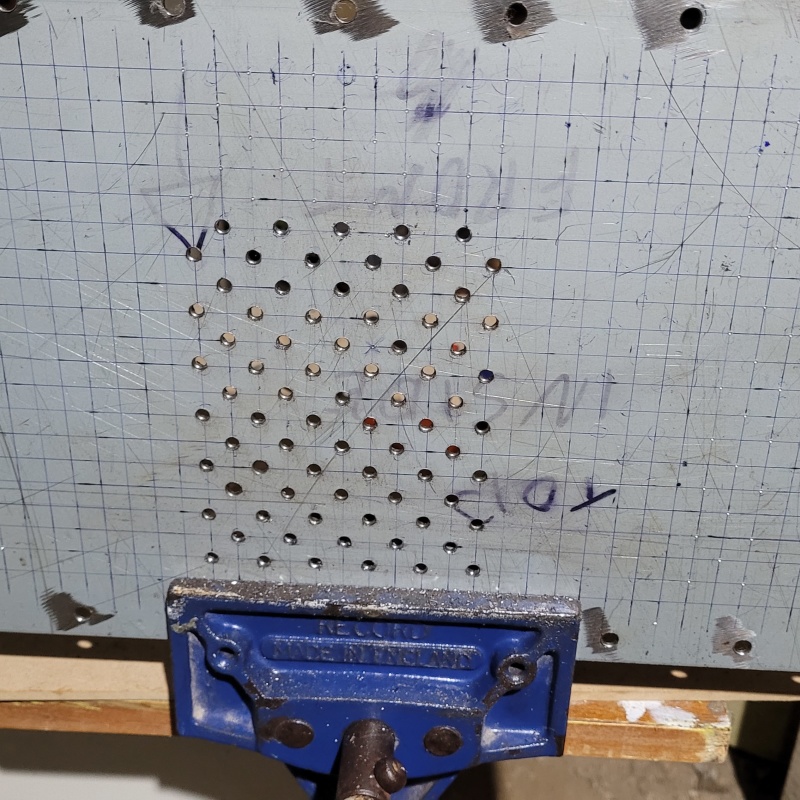
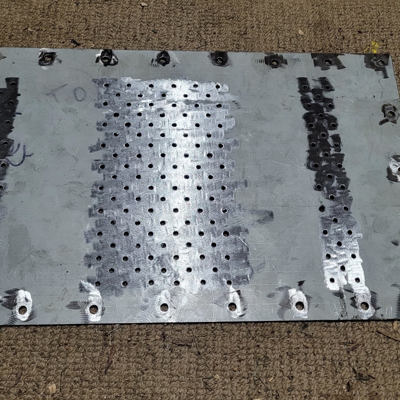
I also started on the vent hole drilling in the top plate. Probably 2/3 of the way done on the first pass out to 4mm. I will go out to 6mm I think.
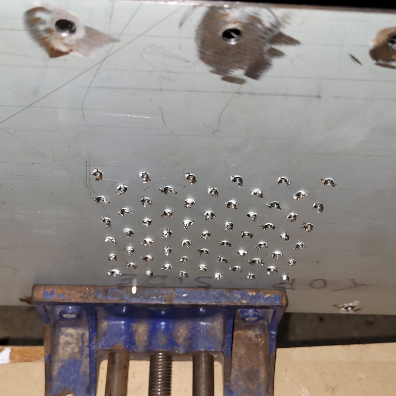
This is what I mean by the 'push through' which leads me to use power tools for deburring.
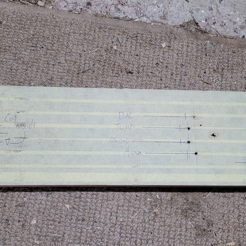
I also finished the drilling for the I/O on the back panel and all of the various things that go in and out of the front panel (metal part). So that's the front back and sides sorted.
The top plate shouldn't take me too long now that I've stated it. I am yet to start the serious work of vent holes in the bottom plate as I need to mount the 2 input selector pcbs before I can.
Once all of the metal is out of the way I will be forced to tackle the tricky stuff on the front panel. LEDs and labels.
|
Post by RdM on Mar 26, 2023 19:57:52 GMT 12
Love that engraving. So crude and so wonderful for it.
This is what I mean by the 'push through' which leads me to use power tools for deburring. Yes wow I see what you mean. What about a countersink bit for metal? Lowered precisely so as to not gouge too much? Drill press, or by handheld eye and feel?
I used to crudely twist a larger size drill into aluminium holes to remove swarf, but it would always grab at some point and nick the circle.
Today I bought a deburring tool from Bunnings, I was going to go there anyway. I paid double for a Noga one with 10 replaceable blades vs a single fixed blade Irwin.
My package of tools including a step drill set has been a bit delayed in the post, but I should have it by early this next week.
|
Post by sadface on Mar 26, 2023 21:05:52 GMT 12
Yes wow I see what you mean. What about a countersink bit for metal? Lowered precisely so as to not gouge too much? Drill press, or by handheld eye and feel?
I used to crudely twist a larger size drill into aluminium holes to remove swarf, but it would always grab at some point and nick the circle.
Today I bought a deburring tool from Bunnings, I was going to go there anyway. I paid double for a Noga one with 10 replaceable blades vs a single fixed blade Irwin.
My package of tools including a step drill set has been a bit delayed in the post, but I should have it by early this next week.
I used to use a twist drill for deburring, and stopped for the same reason: Some holes ended up bigger than I wanted after drill bit grabbed.....
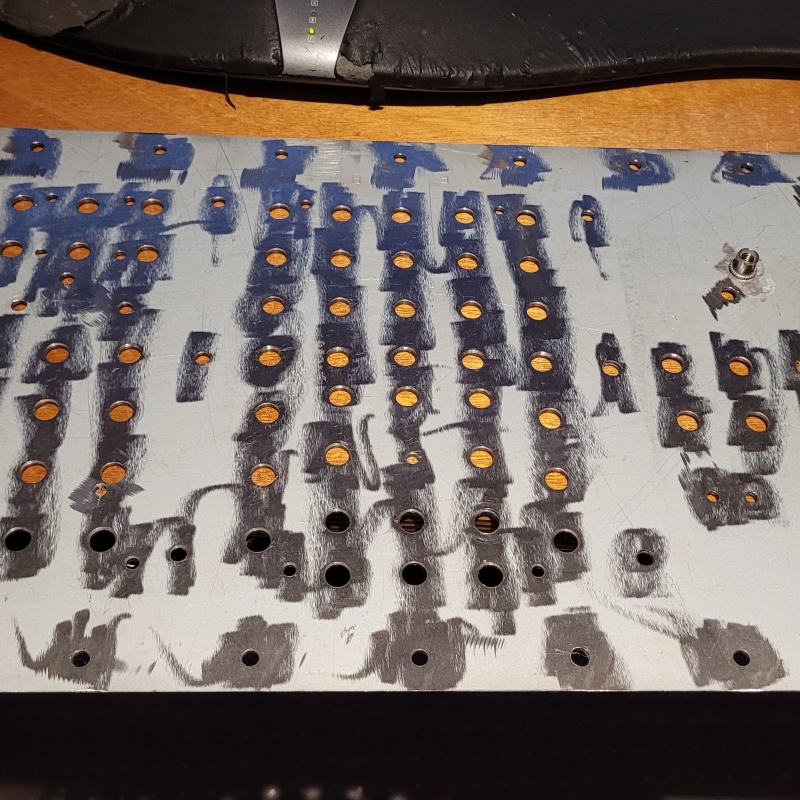
An hour and a half this evening and I'm here. First pass of drilling done with a quick lick with the power file to clear up. This is the 'underside' that had all the material pushed through. Which is actually the top side which will be on display later.
The mighty step drill bit keeps going like the energizer bunny. I should probably give it a sharpen soon, it must be getting close to having done 1000 holes by now.
Out to 6mm now and then the serious deburring work.
|
Post by sadface on Mar 29, 2023 20:04:27 GMT 12
I had a bit of time the last couple of evenings.
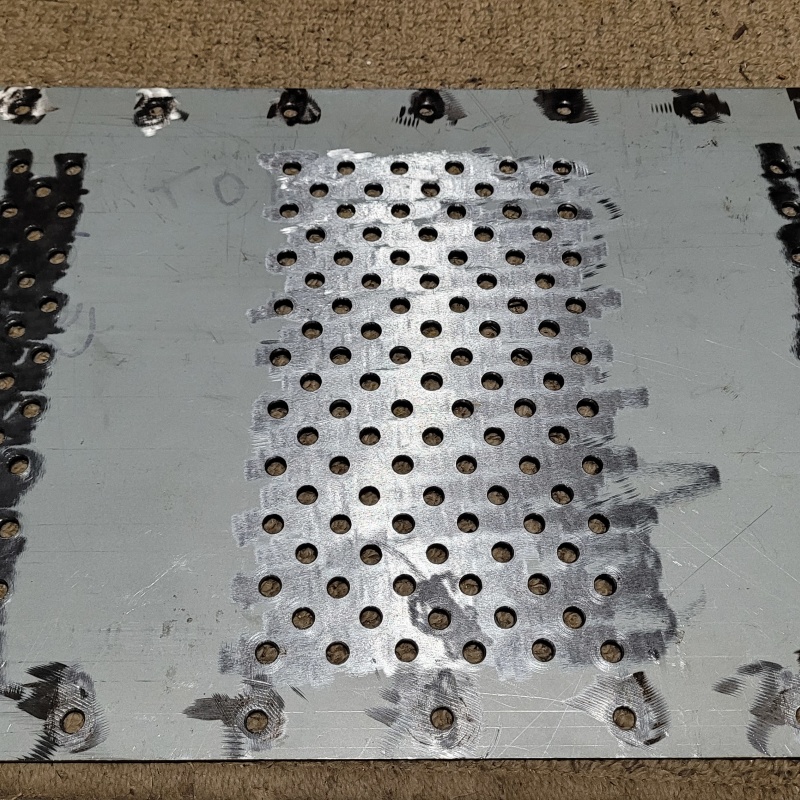
The top plate is done! Drilled out to 6mm, filed and deburred.
Top side
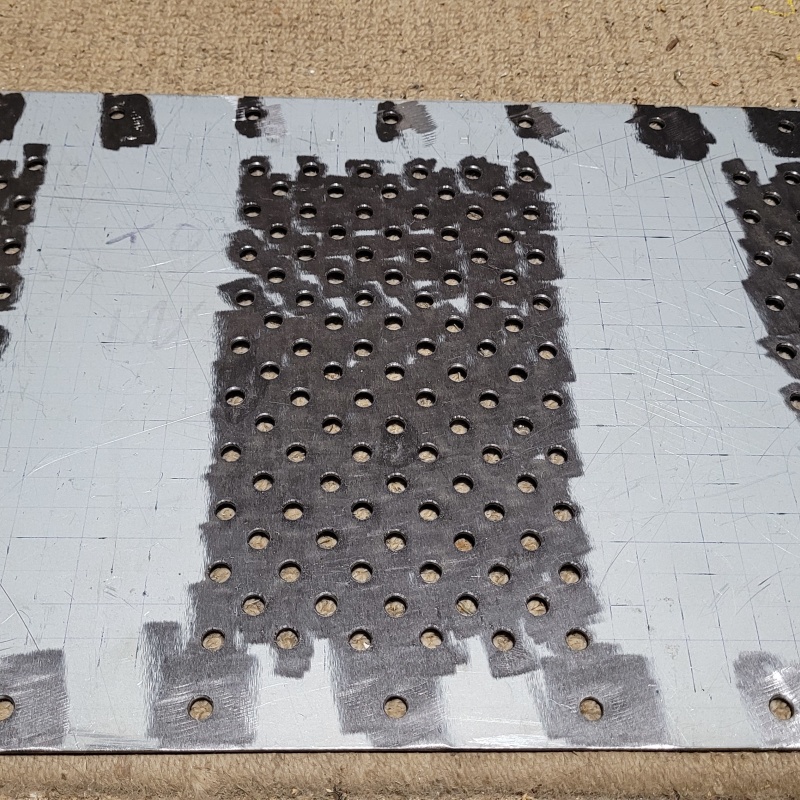
Under side
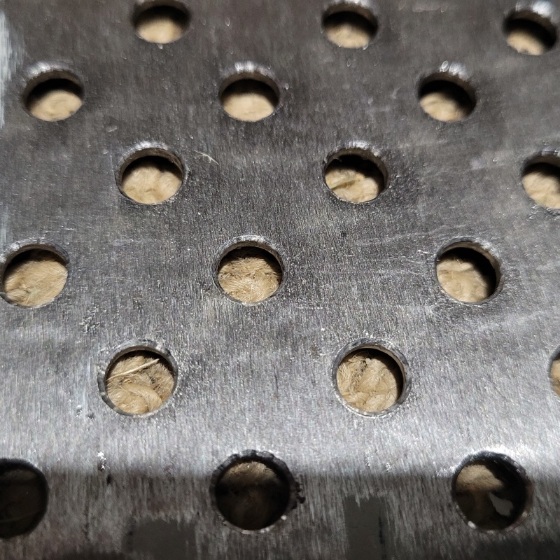
A close up of how the holes come out with my process. I really like the effect of deburring with the step drill.
On to the front panel.
|
Post by RdM on Mar 29, 2023 21:07:10 GMT 12
I had a bit of time the last couple of evenings.
The top plate is done! Drilled out to 6mm, filed and deburred.
[...]
I really like the effect of deburring with the step drill.
I wonder what you're planning cosmetically for the exposed top plate after all that work. I quite like the old-fashioned crinkle black look, but there are plenty of other finishes available, I imagine.
I mean, to conceal flaws on the surface. Or maybe it can be re-surfaced? What can be imagined? ;-)
Nice comprehensive & focused work, anyway! ;=})
|
Post by sadface on Mar 30, 2023 7:10:36 GMT 12
I will spend a bit of time with random orbit sander to smooth things out as much as I can.
Rustoleum hammered antique pewter should do the rest. My favourite finish.
We'll see just how forgiving it is with those angle grinder gouges.
I might leave the under side of the bottom plate less 'finished' to see just how much can be concealed.
|
Post by sadface on Apr 1, 2023 20:17:22 GMT 12
A rainy day meant there was plenty of time for arts and crafts time today.
I had a good couple of hours worth of progress.
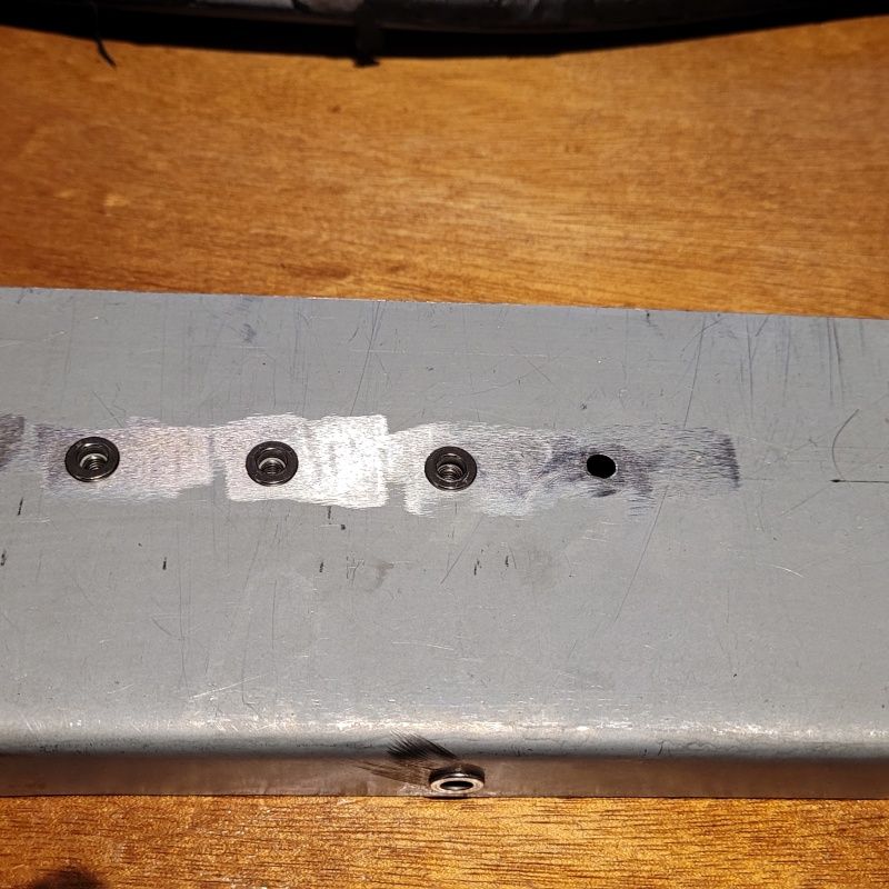
The bottom plate is all done: The last pcbs mounted. Vent holes drilled and the big M6 rivet nut for the power transformer in place. That last bit was a bugger, I had to use a vice to actuate the grips on the rivet nut setter as I simply don't have the grip strength.
I tidied up some bits on the front and back panels. Here's a test fit of the input board. Nice fit if I do say so myself.
I also placed a bunch of rivnuts on the on the brackets for cable routing later.
That is basically all the metal working for the time being.
I have no excuse not to start the tricky stuff I have been avoiding with the front panel!
|
Post by sadface on Apr 8, 2023 12:00:35 GMT 12
G'day Guys,
Some good progress over the last week.
Some serious test fitting. Everything mounted up.
Front panel installed.
These flexible couplers are a godsend.
They work nicely to correct for the various inaccuracies that have accumulated over various parts that add up to a bit of a misalignment between the volume pot and the hole in the front panel. One has the grub screws that came with it and one has some m5 hex bolts from in my stash of salvaged bolts. I will think I will get some stainless hex bolts for final assembly rather than the grub screws.
Since nothing more will change with the top plate, I decided to give it a finish sand with some 240grit and chuck on some etch primer.
Really nice looking I think.
I really like the colour of etch primer, I think on some future build I might just etch primer and give it a clear coat.
After some practice with my letter punch set, I have decided that I will get the front panel laser etched after all.
I also got a bit overzealous with some hole drilling and drilled out the LED holes to 8mm by accident. I think this will work out but I wont know until the LED mounting clips arrive from Aliexpress. So pending LED clips and laser etching there is nothing left other than wiring and test assembly before I can do the serious finishing work.
|
Post by colinf on Apr 8, 2023 17:48:35 GMT 12
I like the colour too. Do you like the matte texture?
AMR-iFi R&D
|
Post by sadface on Apr 8, 2023 19:57:55 GMT 12
Yeah I love the matte texture. I think if one was to consider this a serious finish and treat it accordingly you could get a really nice finish.
|
Pundit

Post by tonyd on Apr 9, 2023 7:35:10 GMT 12
I have used etch primer for refurbishing Garrard turntable platters. It's great to use because it seems to spread very evenly, and dries very quickly. No clearcoat, just the matte finish:
Great thread btw ...
|
Post by sadface on Apr 9, 2023 19:39:57 GMT 12
That is a lovely finish.
It seems a bit darker than the primer I'm using.
What product was it?
|
Pundit
Post by tonyd on Apr 10, 2023 8:14:35 GMT 12
That is a lovely finish. It seems a bit darker than the primer I'm using. What product was it? Wattyl Killrust Super Etch Primer - Black (sometimes labelled Matte Black).
|
Post by sadface on Apr 10, 2023 21:34:15 GMT 12
The category (5, 5e, 6 etc) doesn’t matter for audio, more the shielding. The 100k pot has a maximum 25k output impedance (2 x 50k || ) so just trying to minimise any external capacitive pickup from the input signal to the pot next to the output from the wiper. The compromise from an unshielded cable is loss of channel separation at high frequencies, and/or increase in RF from the input signal, if present. As the casing is metal and is grounded, the risk may be small. Twisting the wires is good!
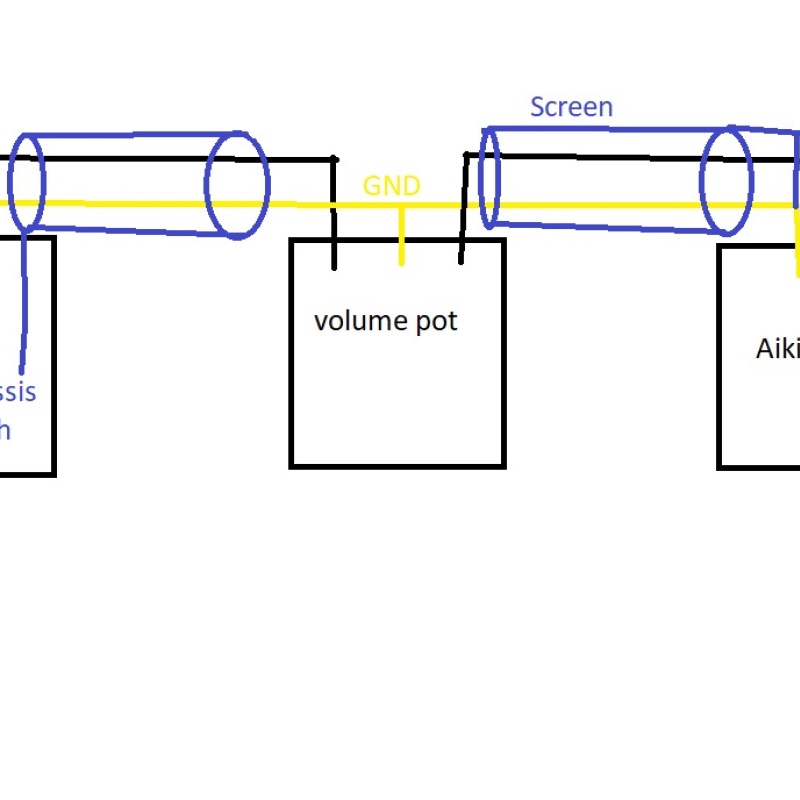
So if I am understanding you correctly.
Important here is the wiring from the 'output' of the volume pot to the input of the aikido.
I have found 2 convenient options for shielded 2 core wire. I tried salvaging some from my stash of various faulty receivers however I couldn't get a matching pair in the correct length.
Jaycar to the rescue. The cheaper option. The twisting of the pair on it is pretty mild maybe 1rpm every 2 inches.
The more expensive and bulky option. 24awg cores instead of 28awg on the cheaper stuff. The twist is maybe 1 rpm per inch. Cotton insulation between the cores and the outer screen is braided.
I'm thinking the microphone wire is worth the extra bulk?
Does this look appropriate for the wiring of the shield or am I best to not used shielded wire from the input to the volume pot?
|
Post by colinf on Apr 13, 2023 18:38:03 GMT 12
That would work fine. Microphone cables are usually designed to be flexible and with strain relief, prob not necessary for internal installation.
AMR-iFi R&D
|
Post by sadface on Apr 13, 2023 21:04:27 GMT 12
Thanks Colin.
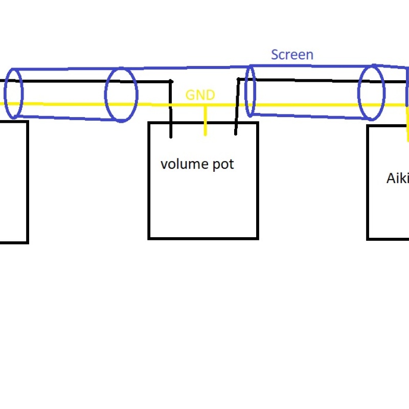
I'm also considering this version.
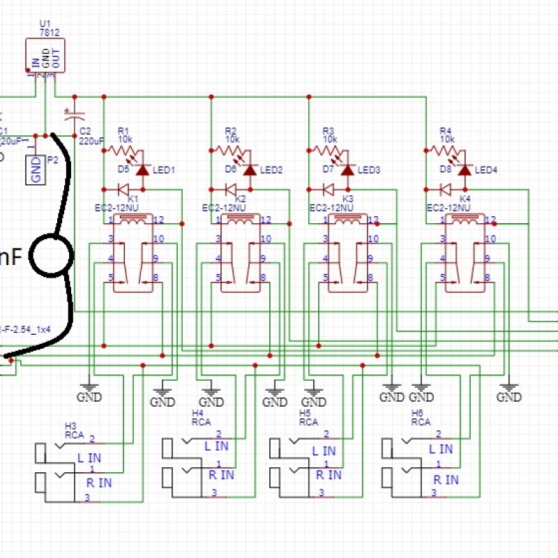
The rca sockets are wired separately to the circuit driving the relay coils. I'm thinking a better location for the shielding going to the volume pot would be straight to the nearest earth which would be the earthing for the relay coil driver section.
Also I am thinking I will solder a 100nF ceramic cap from the 'input' ground attached to the RCA sockets to this earth point underneath the board. Like so:
|
Post by colinf on Apr 14, 2023 18:37:21 GMT 12
It’s best to connect the audio shielding to the audio ground. The second diagram for pot wiring is also fine, there are many ways to wire it. You can use the 100n cap for grounding the relay power to the audio circuit, but it will be floating with no DC connection. I’d use a resistor in parallel with the cap, say 100 ohms. Also note that the LEDs are the wrong way around on the schematic. Additionally, when a source isn’t selected, it gets shorted out to ground, which could cause them to not work as intended. eg. a CD player which derives its headphone output in parallel with the output, but still connected to your input switching. I’d use a resistor between each relay contact off leg and ground, say 22k.
AMR-iFi R&D
|
Post by sadface on Apr 15, 2023 21:50:41 GMT 12
Hi Colin,
Yeah that reversed diode turned up when I ran the first test on the input selector board.
I will fix this on the next version of the input selector board. In the mean time I've just reversed the polarity of the diodes on the board.
Interesting suggestion regarding putting a 22k load in series with the ground for unused inputs. I will definitely do that.
Sadly, with the current version of the board I can't retrofit a 22k resistor as the relay pins connects directly to the ground plain.
|
Post by sadface on Apr 17, 2023 20:31:49 GMT 12
Regarding the relay input selector. Would a better design simply have the relay connected to nothing rather than ground when not in use?
|
Post by RdM on Apr 17, 2023 20:47:55 GMT 12
I was just waving an oscilloscope probe around this afternoon and it picked up all sorts of waveforms connected to nothing.
So maybe a certain alternate resistance is good?
|
Post by colinf on Apr 18, 2023 7:01:52 GMT 12
It’s good to have some sort of resistance, mainly there to have any source that has an output capacitor settle at 0v before switching There is lots of RF around these days, and the oscilloscope shows it! That’s why I’m a bit hyper about RF ingression into audio circuits.
AMR-iFi R&D
|
Post by sadface on Apr 25, 2023 21:35:49 GMT 12
G'day Guys,
A wee progress update.
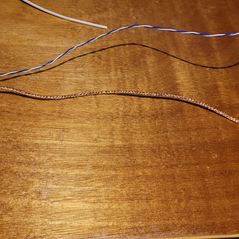
I've decided to attempt making my own shielded wire.
The stuff that was readily available locally was not quite what I was after. I've had a bit of a look around the usual suppliers like Mouser, Element 14 et al. Nothing here unless I want to order a roll.
So I've ordered some 2mm braided copper shield from ali express to experiment with. I will see if I can slide some good old fashioned cat5e through the shield neatly and then cover it with some ptfe braid.
I'm all out of ideas as to retro fitting some series resistance to the source selector. I was thinking of scratching off the traces and bridging with 22k resistors to ground.
However I poured ground plane on both the top and bottom of the pcb. Bottom side not so difficult but getting under the relays on the top side..... I will just have to forget about this bit for this build I think.
While pondering these issues back and forth I've finished up the metal working and primed everything ready for paint pending the test build.
I had a wee issue with the priming. I accidentally purchased 2 slightly different cans of primer. One "grey etch primer" and one "grey metal primer".
I discovered this at the point where the etch primer ran out mid coat and I went to use the 2nd can only to discover it was a different colour.... So the etch primer was still wet when the grey metal primer was applied. There is some slightly dark patches where the 2 primers mixed. I'm hoping this won't cause issues later.
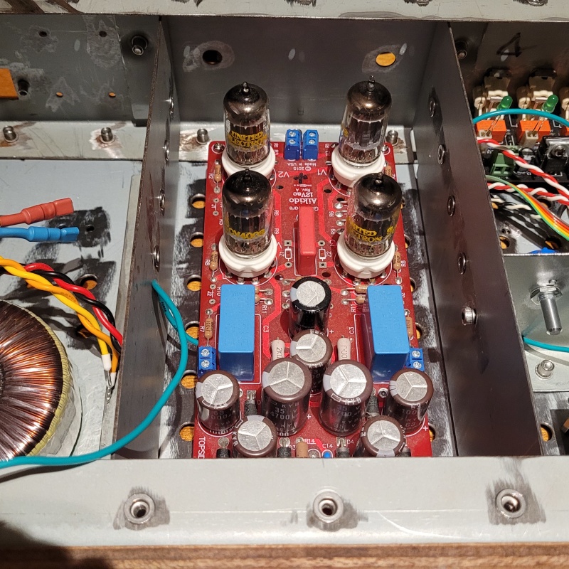
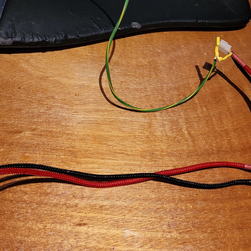
I've also been tackling the wiring.
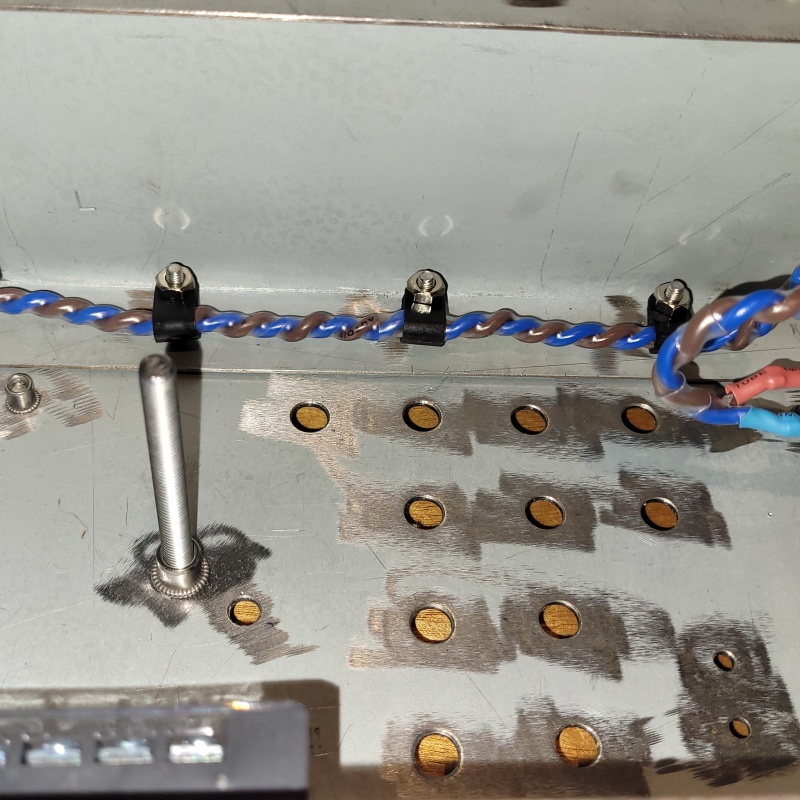
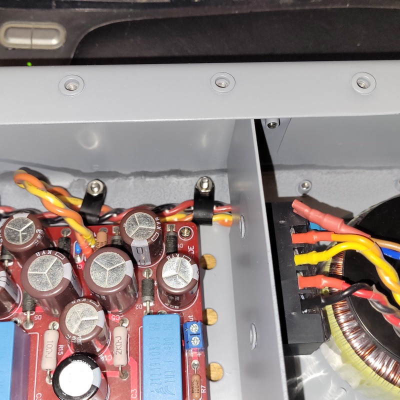
Mains side done.
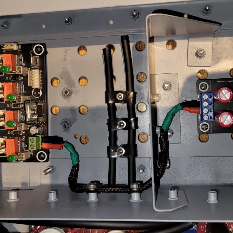
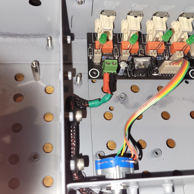
Routing for the signal wiring from the volume pot to the aikido board.
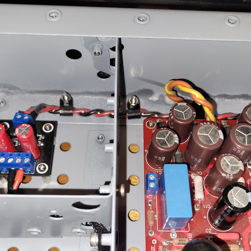
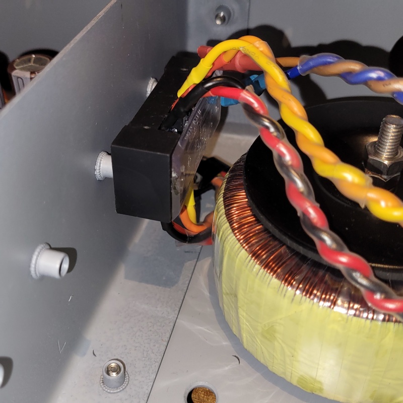
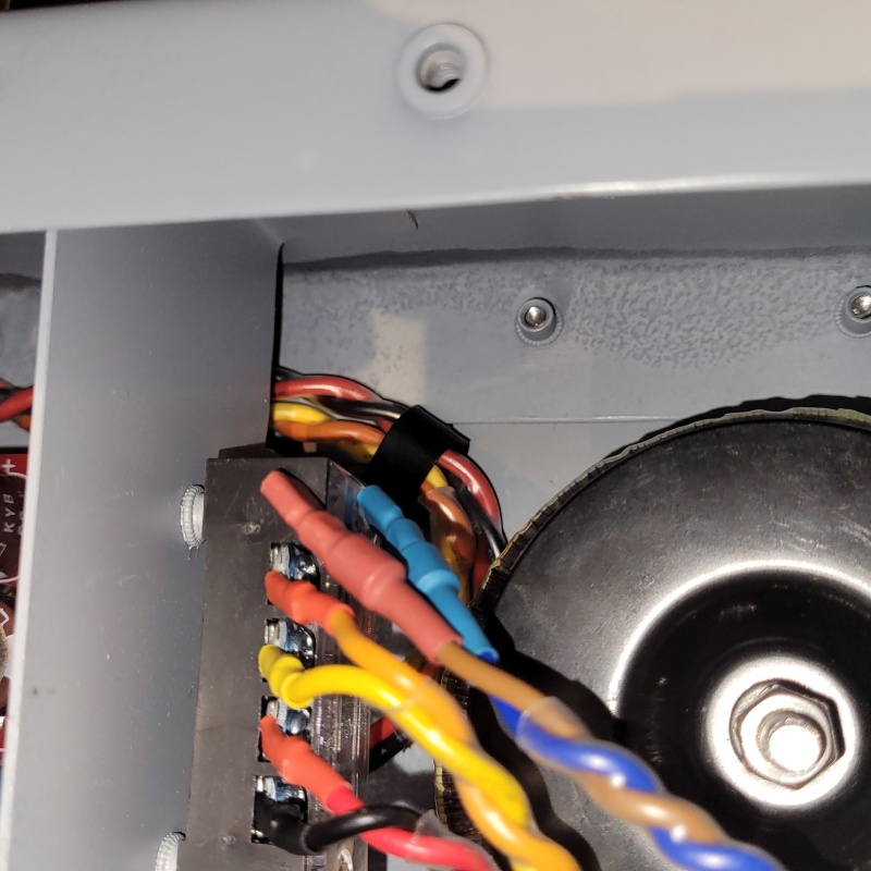
Transformer secondary wiring.
Power supply wiring for the source selector.
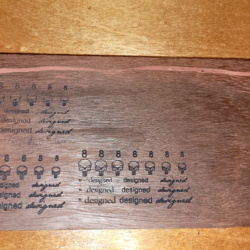
I also got my wooden front panel back from laser testing. It came out looking pretty good.
I will go with bottom left option, however I will be using a larger font size.
After a light sand with some 240 grit and a bit of danish oil, this is the result.
|
Post by colinf on Apr 30, 2023 19:54:06 GMT 12
|
Post by sadface on May 26, 2023 22:21:11 GMT 12
G'day Guys,
I've been beavering away bit by bit.
I've got all of the input side wiring. The copper wire braid worked quite well.
Braid.
Braid over some cat5e
Heatshrink over the braid.
PTFE braid over the heatshrink.
The finished product, both sides of the volume pot. I decided to wire the shield on input side to the earth on the input selector board.
I've also sorted out the wiring for the selector switch.
|
Post by colinf on Jun 3, 2023 19:11:09 GMT 12
Very neat! The homemade shielded wire looks good. Are you able to measure its capacitance?
AMR-iFi R&D
|