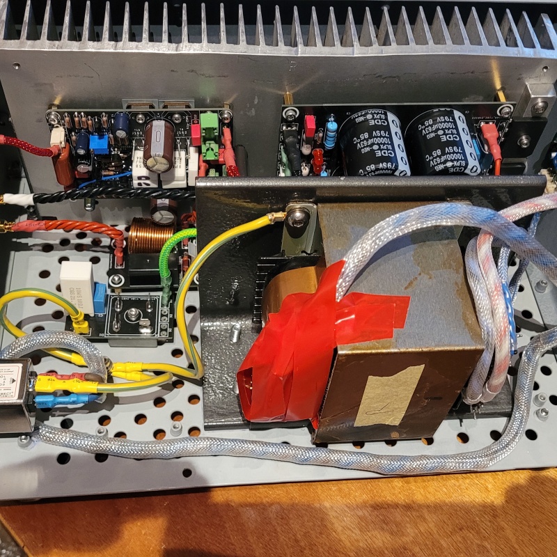
Post by sadface on Feb 24, 2024 20:47:26 GMT 12
G'day Guys,
Time to introduce my next build.
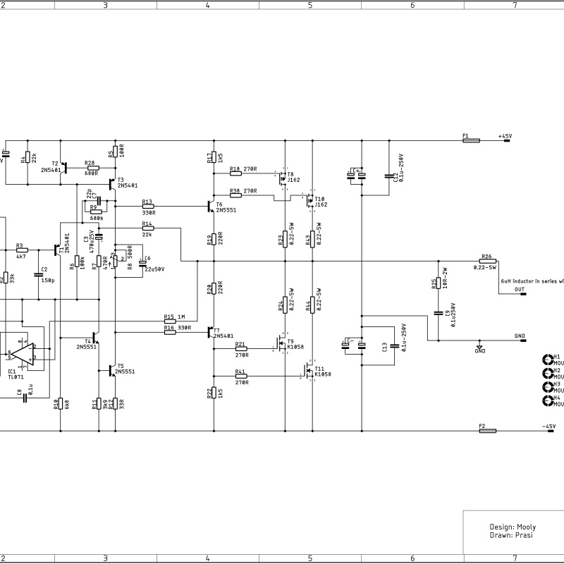
This will I will be moving to mosfets. Here's the schematic:
A nice an simple design. Singleton input which is a bit less common but should make for a nice sound.
This time round I am going the monoblock route for a couple of reasons: 1) I think their cooler than stereo amps.
2) mono construction, better blah blah blah.....
3) My racking situation is much better suited to my power amps being monos.
4) I like making extra power supplies etc.
I will be building my chassis from scratch again: 1) I have the tools, sheet metal is relatively cheap.
2) Ali express cases tend to not be my style and shipping is horrendous to NZ.
3) I like making things myself for the sake of making things myself.
4) I can get exactly what I want instead of being constrained by somebody else's engineering/design choices.
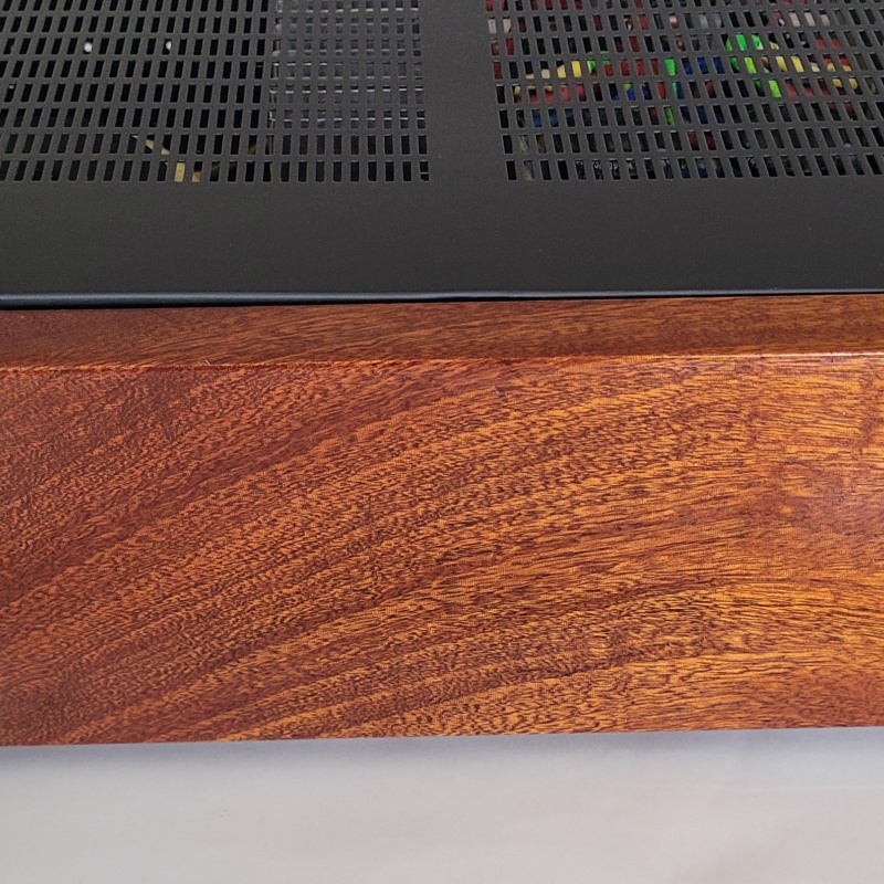
Following my recent builds, this one will have some nice chunks of mahogany up front. Nice clunky push type coffee machine power switches. This time round I will play with some VU meters.
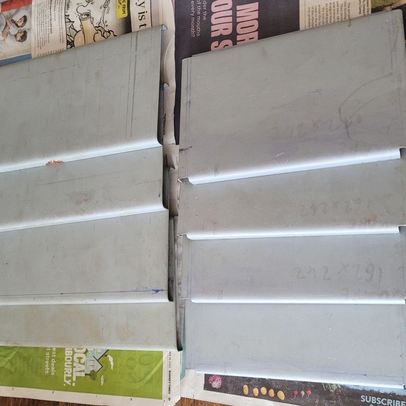
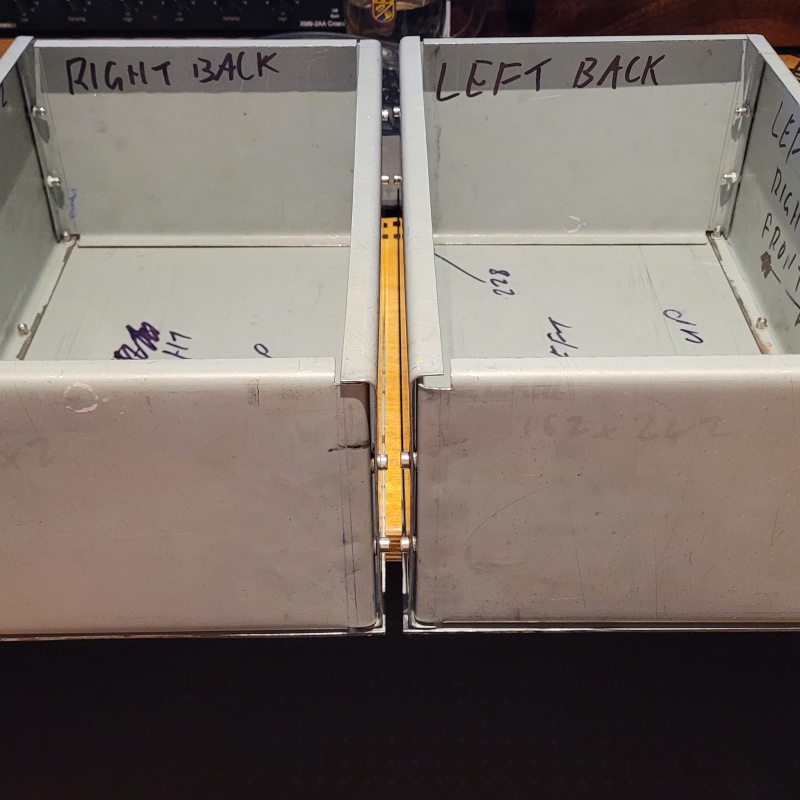
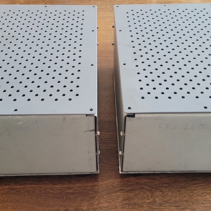
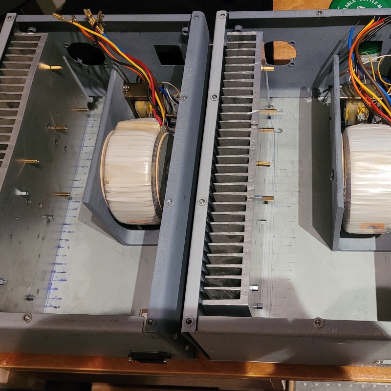
I started the build over the Christmas holidays when I had a bit of 'noisy time' available for the initial sheet metal cuts. Front back and sides are 1.2mm Top and Bottom are 2mm. The basic design is a repeat of my 12vac aikido preamp build. Which was of course a blatant ripoff of the old DesignBuildListen EZchassis. Here's the basic cuts
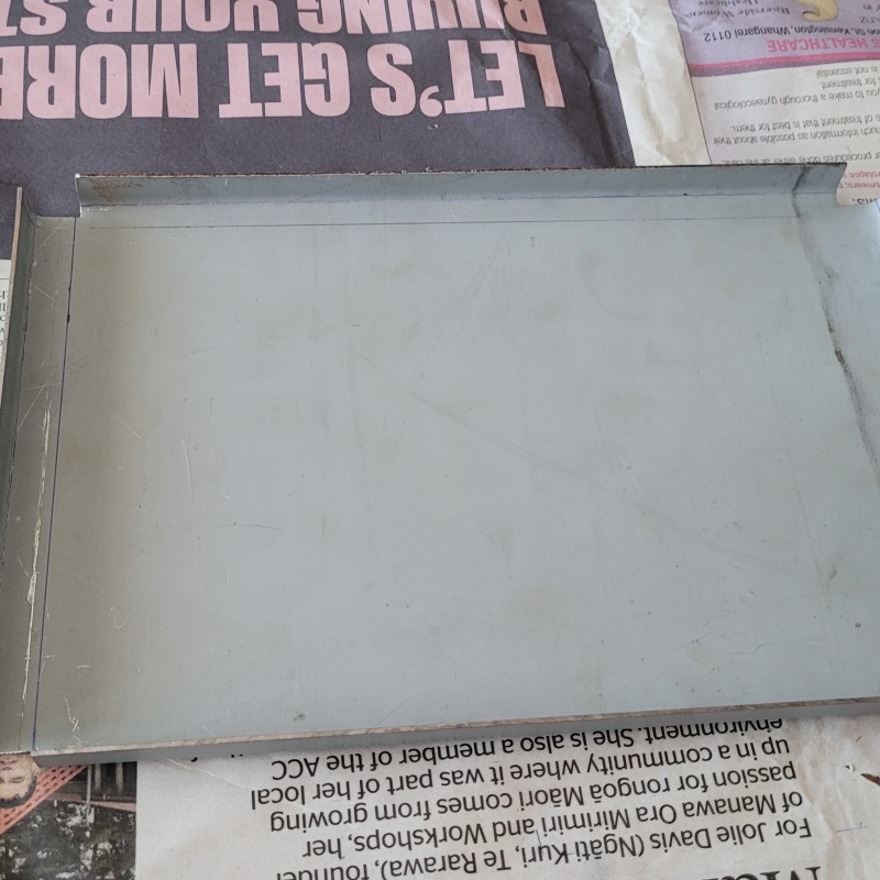
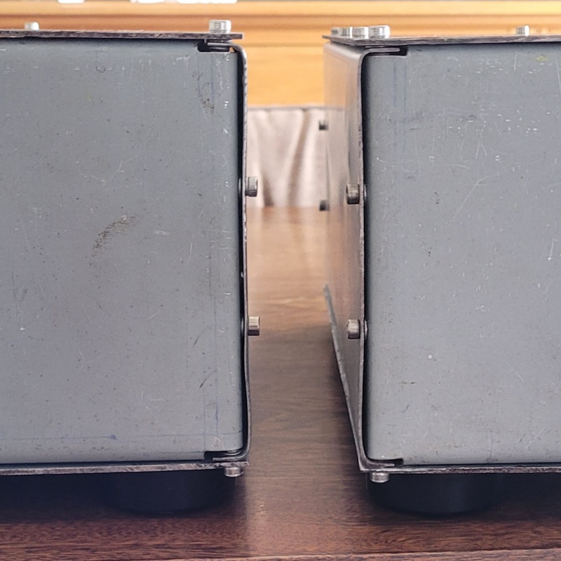
Front, back and sides all folded up.
My sheet metal work is getting better. My cuts were more accurate this time as well my folds. Tolerances are getting tighter.
Most of my issues this time around have been issues of design. Eg: hole centres that didn't account for everything they should....
I am also using a lot less bolts this time having been through the nightmare of my 12VAC aikido build. I had an unnecessary amount of bolts which became quite difficult to align nicely after a few mistakes were made. Mistakes in metal multiply and cascade. Metal seems to be very unforgiving.....
We will see how well I can cover my mistakes at the end of the build.
Plenty of space inside for goodies.
|
Member
 
Post by snewt on Feb 25, 2024 7:04:45 GMT 12
As always I'll look forward to following your progress.
|
Post by colinf on Feb 26, 2024 21:43:00 GMT 12
Another fun project! Add a diode (1N914 etc) from T5 collector to T4 base. Direction is K at T5 collector and A at T4 base. It’s to relive high stress on T5 that might cause it to blow, during clipping.
AMR-iFi R&D
|
Post by michaelw on Feb 27, 2024 10:01:38 GMT 12
~ 60 watts is where magic happens
Harry Pearson, The Absolute Sound 1979
|
Post by sadface on Feb 27, 2024 19:16:48 GMT 12
My guess as to why the 60w is a sweet spot comes down mostly to complexity.
Go above 60 odd watts and the number of stages goes up, complexity goes up.
Things become much harder to finesse.
I have a pcb set for a 200w into 8ohm amp design.
It uses something like 30 transistors per channel.....
|
Post by sadface on Feb 29, 2024 21:00:28 GMT 12
G'day Guys,
Another progress report:
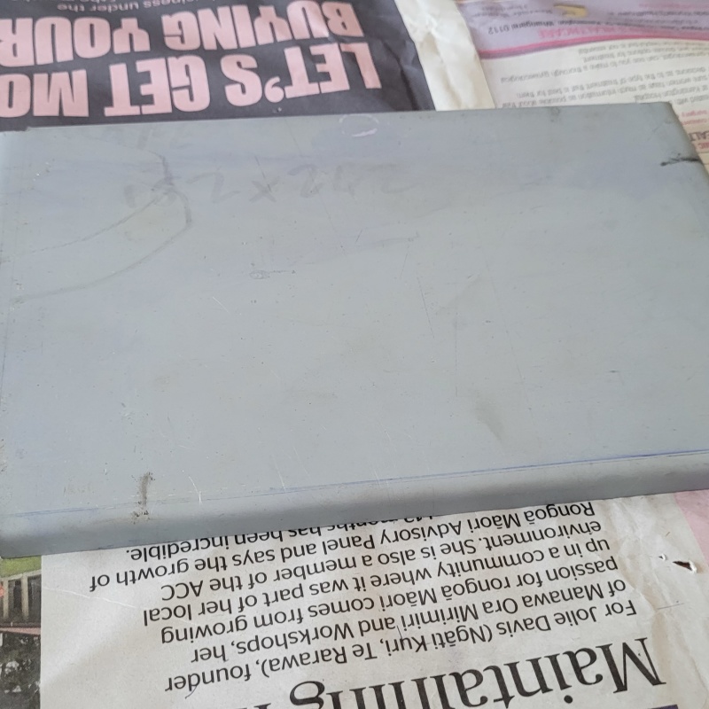
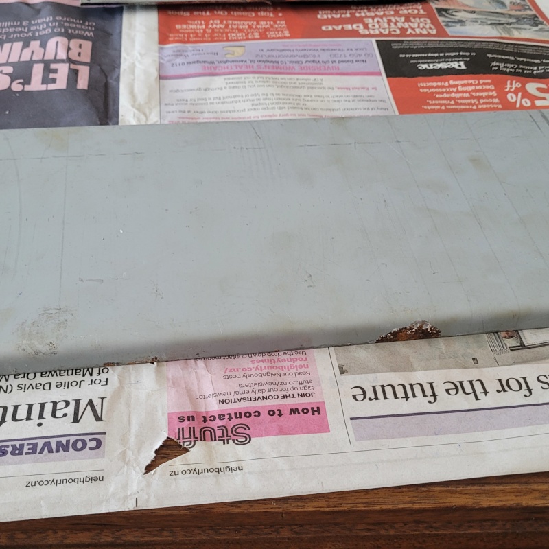
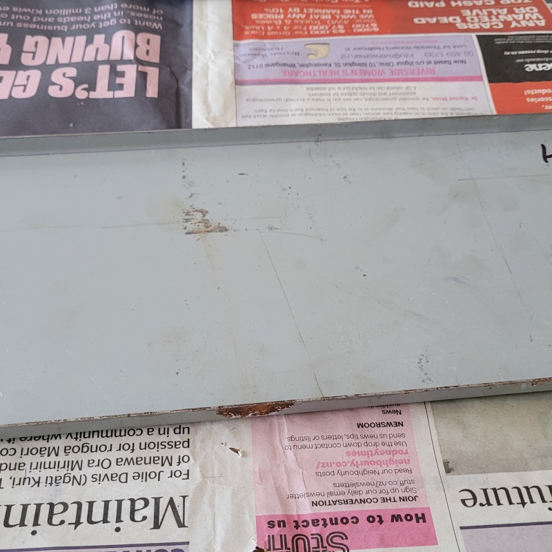
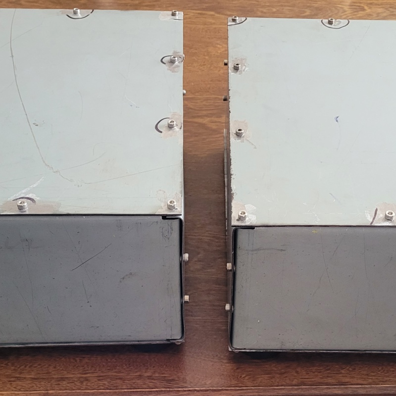
The lids are done except final paint. There was a bit of fun involved here.
In my initial plan for the chassis I decided to go with my hole centres 5mm from the egdes. This created some problems mainly due to not accounting for the bend radius......
So when it came to putting the rivet nuts into the front back and sides I had to move the holes a little bit away from the bend.
Which mean the holes I had already drilled on the top and bottom where not quite in the right place.....
On the bottom where nobody should be looking, I simply filed the holes into slots and called it a day.
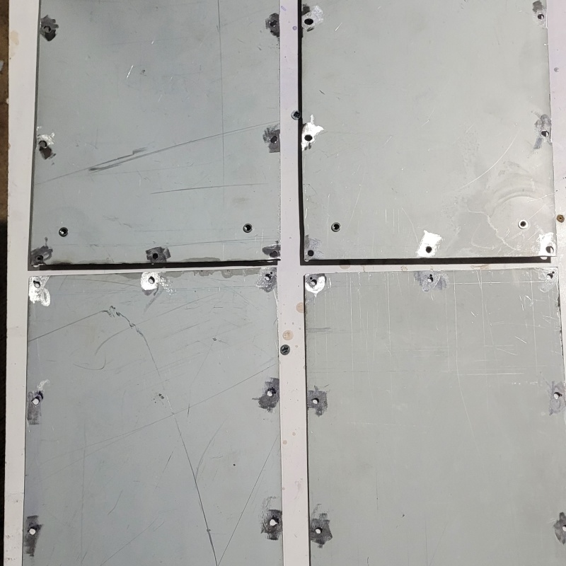
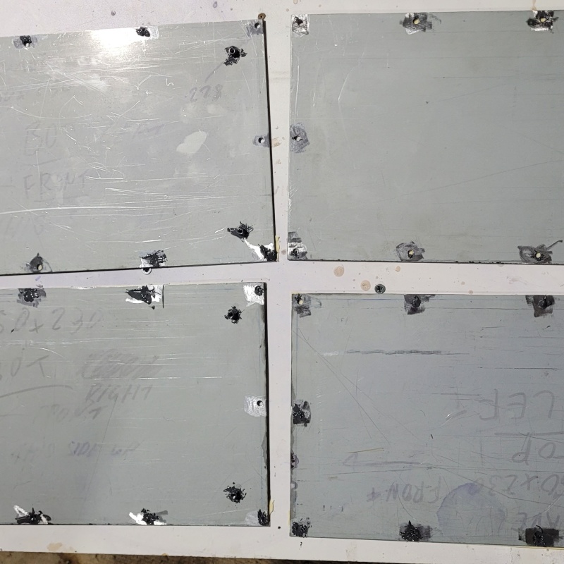
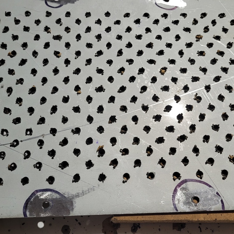
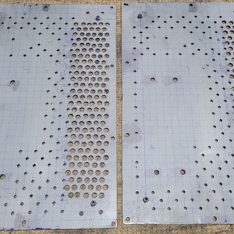
On the top plates which I did 2nd I simply drilled another set of holes as my original holes were only 2mm as I hadn't drilled them out yet. This allowed me to move the holes over sufficiently to make everything fit nicely but it did leave some tiny little divots around the holes which just weren't pretty enough for an A surface like the top plate. There was also one or 2 holes where something wandered and the hole needed to be slotted a little bit..... Exhibit A
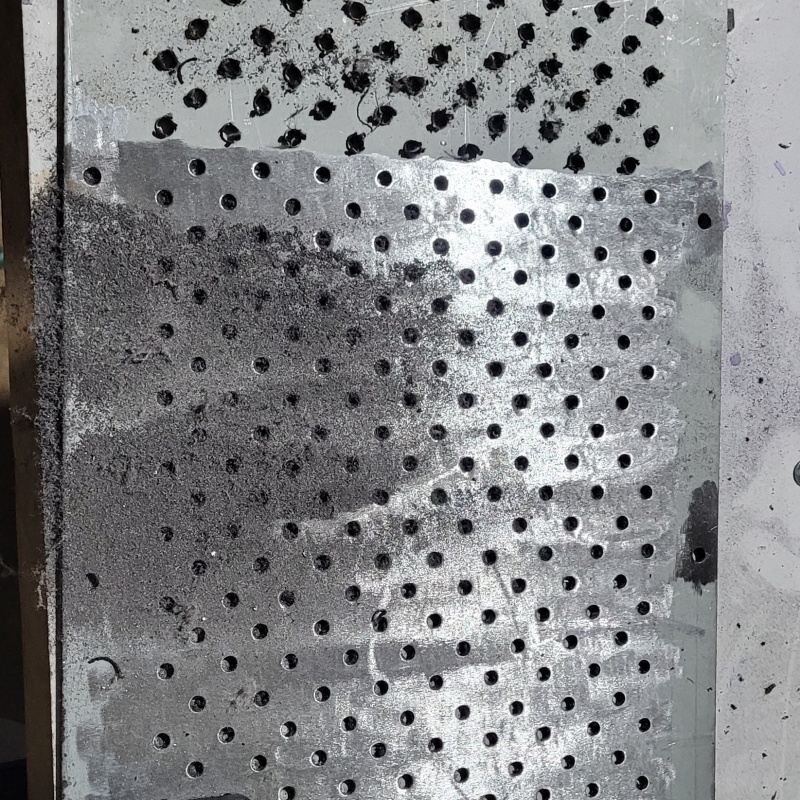
So in a moment of genius. I wandered if I could simply bog the mistakes up. A wee google search turned up this magical stuff: So my evil plan was to goo up my mistakes and then redrill out the holes where they should be:
After a bit of sanding flat and a bit of drilling it was like I had never made design errors or been in a rush on my metal working at all!
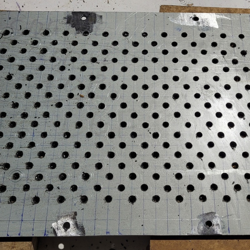
Then it was time I started on vent holes!
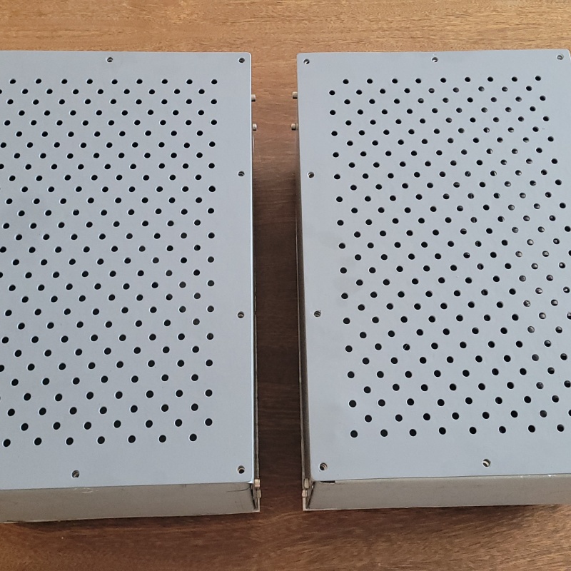
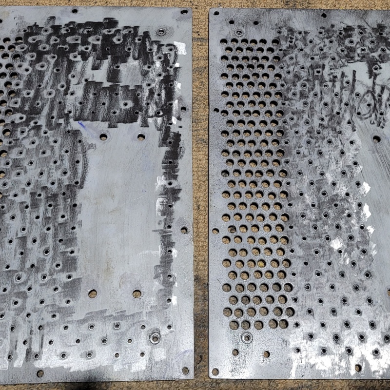
For the top plates I ended up with 270 holes in each one. I think it took me about an hour and a half to rule them out and centre punch them. My poor wife had to put up with all that banging. My 2 year old girl had great fun helping daddy make all that noise. She loves playing amplifier.
I think it took me about 4 hours worth of drilling for the pair.
And then there was another couple of hours to de-burr the holes. My trusty finger sander came to the party here to get rid of all of the 'spew' on the back side of plate from the step drill.
After all of that. A bit a lick with a 240 grit pad on the random orbit sander and a couple of coats of etch primer and voila!
|
Post by sadface on Mar 7, 2024 20:50:23 GMT 12
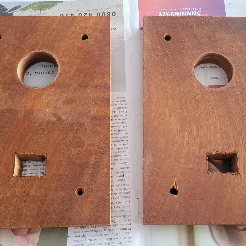
Progress progresses. I was allowed a little bit of cutting time amongst the weekend's chores. -I cut out the mahogany front panels. -Cut the holes for the power switches -Drilled the holes for the VU meters. -Drilled the holes for the bolts to mount to the steel inner front panel.
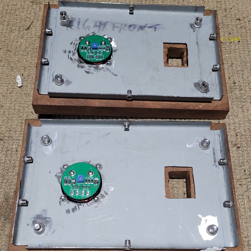
I was also allowed to do the steel work too! Jigsawed out the power switch holes drilled out the VU meter holes drilled and rivet nutted the holes to mount the mahogany 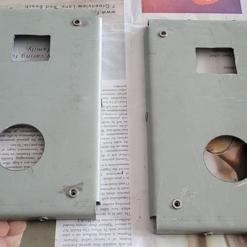
And a test fit:
Fitting the VU meters took much longer than I would have expected.
The meters are 46mm. The closests hole saw I have is 44mm. My cheap holesaw really struggled on the steel. It seems to simply heat and stretch the steel until it was thin enough and work hardened enough to just snap off inside the holesaw.
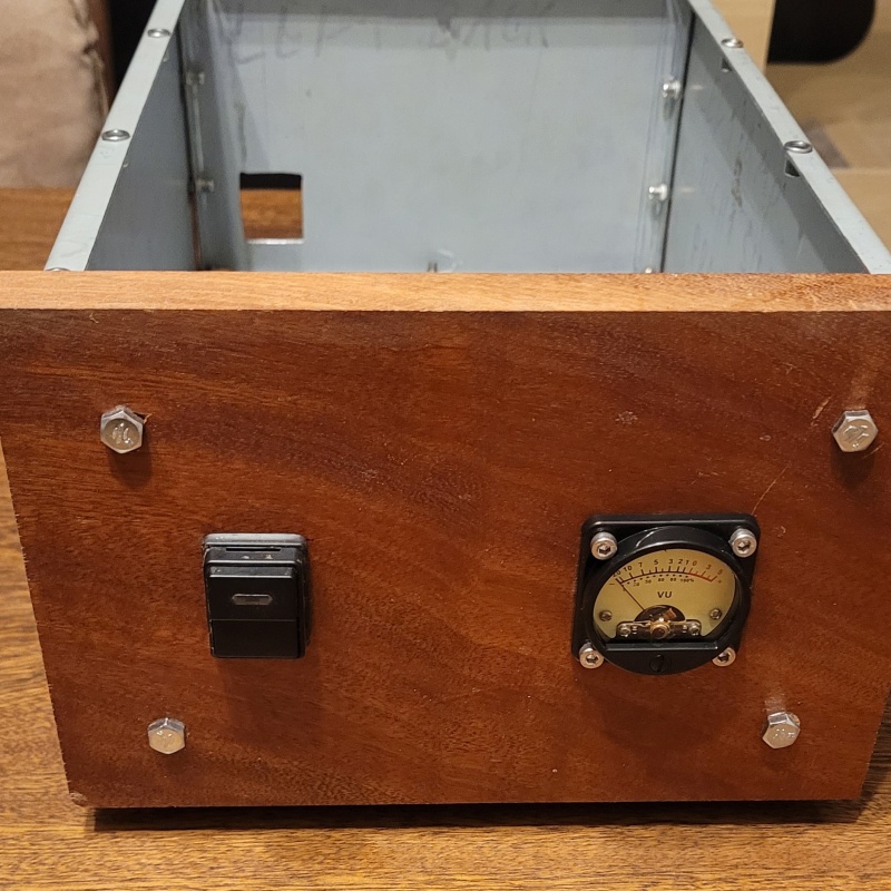
I used a 60grit flap wheel to take out the extra 2mm and boy does it take a while on mahogany. This stuff is hard as nails. Same on the metal. I actually did them both at the same time with the wood mounted to the steel to make sure the finished holes matched up. Then come the harder job of dealing with the mount holes for the VU meters. If I was smart I probably would have used some plain old wood screws.... But I am not. I wanted hex head caps screws like everywhere else on my builds. So.... 30mm m4 bolts through the mahogany and into a rivet nut. My drill press has a decent bit of runout so it was quite difficult to transpose the holes through the mahogany accurately onto the steel. I managed to place the rivet nuts with decent accuracy. There was the small issue of the overhang of the flange on the rivet nuts fouling the hole for the VU meter but my trusted power file and a 60grit belt dealt with that. Some inaccuracy remained after all was done and the meters weren't quite level. So I drilled the holes on the VU meters out an extra 1mm which gave me enough wiggle to straighten things up. 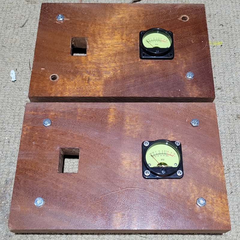 Not enough dummy bolts but you get the idea. Back side. Also in the process, the m4 bolts to mount the wood to the steel became m6 after some alignment issues..... And a proper test fit. Everything straight and level and purdy looking.
I will be using some nicer bolts in the end but thats a ways away at this stage.
|
Post by RdM on Mar 7, 2024 21:50:07 GMT 12
[ ... ] And a proper test fit. Everything straight and level and purdy looking.
I will be using some nicer bolts in the end but thats a ways away at this stage. I really appreciate and like your progress reports, but ... (and I hope you won't mind my critique ;- ) For, and in my aesthetic appreciation ... why would you even need or want bolts visible in the front of the front panel at all? Too late now, but surely it could just have easily been attached from the back, from inside? And the same for the meter? (If not, get plain flat black bolts for it! ;=}) Cheers and regards :-
|
Post by michaelw on Mar 8, 2024 14:25:19 GMT 12
I like the DIY semi-industrial look 
|
Post by sadface on Mar 8, 2024 21:30:16 GMT 12
I've tried fastening from the inside on previous builds. It does give a nice clean look but it was also a bit of a pain in the backside to fasten inside cramped chassis. I also quite like the industrial look of nice fasteners. I am trying to find some black bolts but no luck so far. I spoke to the boys at the bolt shop in Glenfield and I was informed that their black bolts are simply an oil coating that will perish and rust over time. Bunnings has nice black painted cap screws in M6 but they dont have m4x30 bolts for the meters. Still looking...
Also I will recess the bolts into the wood for a nice flush finish like on my last built which I really liked the look of. The black bolts matched the black power switch and black chassis really nicely.
This build will be black chassis also. I am toying with the idea of just sticking to stainless all round. Black chassis Stainless bolts Mahogany front Yellow meter
I figure the stainless bolts will match the stainless elements inside the meters.
|
Post by RdM on Mar 8, 2024 21:44:15 GMT 12
I've tried fastening from the inside on previous builds. It does give a nice clean look but it was also a bit of a pain in the backside to fasten inside cramped chassis. I also quite like the industrial look of nice fasteners. I am trying to find some black bolts but no luck so far. I spoke to the boys at the bolt shop in Glenfield and I was informed that their black bolts are simply an oil coating that will perish and rust over time. Bunnings has nice black painted cap screws in M6 but they dont have m4x30 bolts for the meters. Still looking...
Also I will recess the bolts into the wood for a nice flush finish like on my last built which I really liked the look of. The black bolts matched the black power switch and black chassis really nicely.
This build will be black chassis also. I am toying with the idea of just sticking to stainless all round. Black chassis Stainless bolts Mahogany front Yellow meter
I figure the stainless bolts will match the stainless elements inside the meters.
Thanks! Nice answer. Cheers and I look forward to progress. I might ask about the meters later, I've been looking at some.
|
Post by sadface on Mar 17, 2024 21:23:37 GMT 12
Things keep moving forward slowly but surely.
Set backs come too. I've recently broken a 2mm drill bit, an m3 tap and an m4 tap.... Taps never seem to break when you are done with them either. Its always about 3 holes from when you would be done.
Heatsink work is always fraught with such difficulties so its about time I introduced the heatsinks!
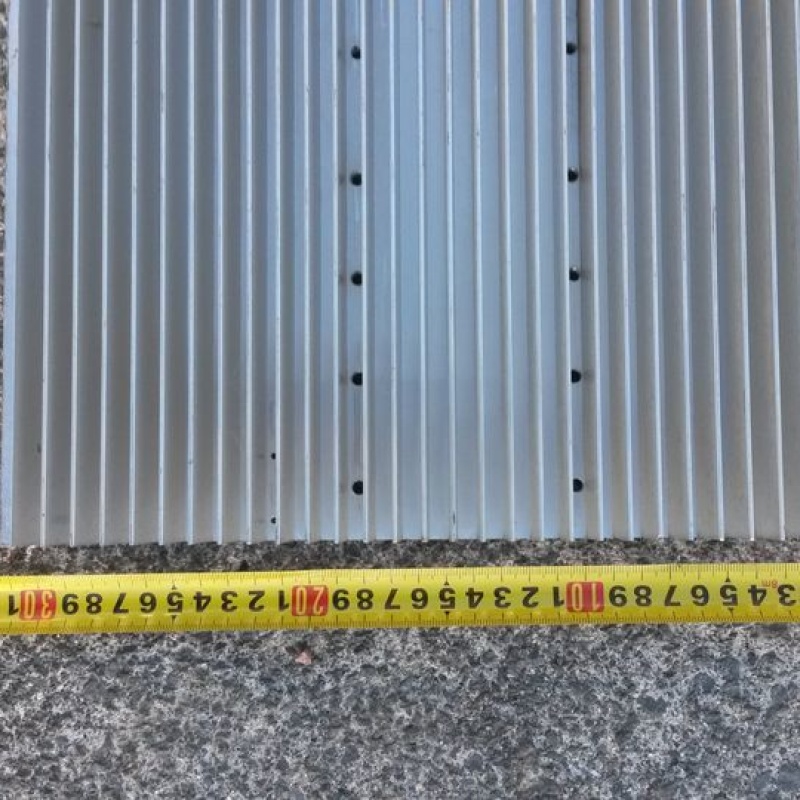
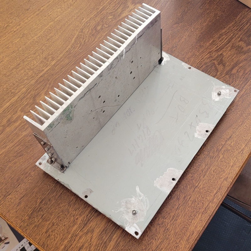
I purchased a heatsink for $50 off facebook market place. 420x40x300. It weighed 5 kilos and was clearly from something industrial. Perhaps an VFD or something similar.
I forgot to take a photo of its original form but here is the photo from the facebook listing.
So out came my trusty reciprocating saw and into 3 pieces it went. It took me about 15minutes to make the 2 cuts. Given it was using a reciprocating saw, it wasn't quite straight. Thankfully the heatsinks will be contained inside the chassis so nobody should notice.
After the cuts I have 3 sections 140x300x40.
Miraculously, the two sections came within 2 grams of eachother at 1.6 kg each. Overkill for some 60wattish amps. A wise old man once said (Nelson Pass I believe) that you can never have too much heatsink.
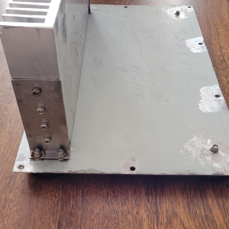
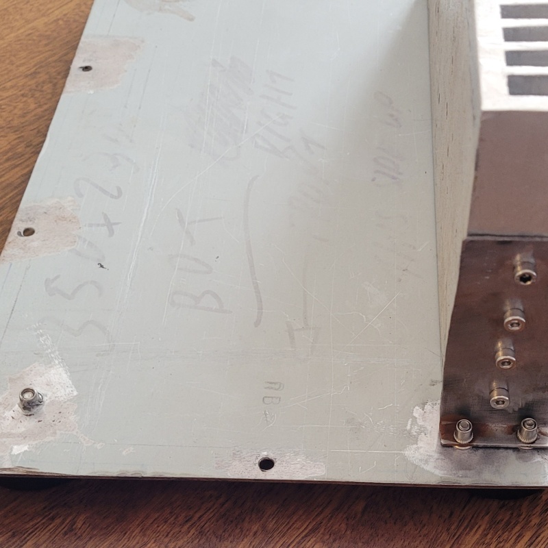
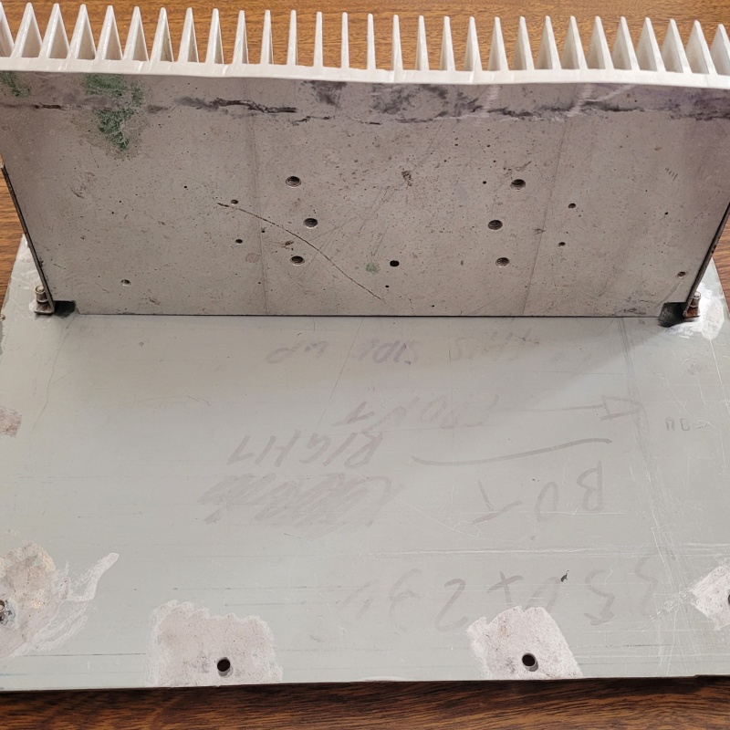
I folded up some brackets out of some salvaged 1.2mm steel. I suspect this stuff is stainless as it just has that colour too it. This one is the "good" channel. The other heatsink had the M4 tap break on the 2nd to last hole...
I had to take some notches out of the bottom corners of the heatsinks to clear the rivet nuts that the chassis feet mount to. Once I am done with working on them, I will tidy up the heatsinks and sand off all the scabbiness leftover from whatever it was used for before.
Next came the purchase of some 125x75x6 steel angle to make a bracket to mount the power transformers. Here is a mockup:
Tonight, I was going through the task of drilling and tapping the M3 holes to mount the amp board and power supply boards to the heatsinks. Firstly I lost my 2mm drill bit quite early. Luckily I had a backup. Next I lost my M3 drill tap 3/4 of the way through the job.
More taps are on their way from Ali Express. After my M4 tap broke a week ago I ordered some extra M3 as well.If I'm lucky, I might get them in another week or so.
In the mean time I've got plenty of metal work to do around the base plate: Drilling vent holes and p clip mounts. I'm also due to start testing the power supply with its integrated speaker protection and also the VU meter.
Plenty to keep me busy while I wait.
|
Post by RdM on Mar 17, 2024 22:46:00 GMT 12
|
Post by sadface on Mar 18, 2024 14:10:51 GMT 12
I'm using the titanium nitride coated version of those.
They worked wondfully until they snapped.
I've ordered the plain hss non coated version thus time. We'll see if their any better.
The m3 and m4 drill taps are especially nice as the drill end is the correct size. M4 needs a 3.2mm drill bit which I've never seen.
|
Post by sadface on Mar 30, 2024 13:02:12 GMT 12
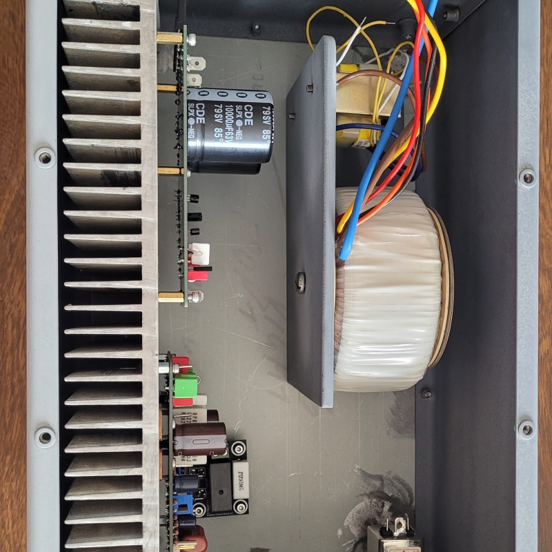
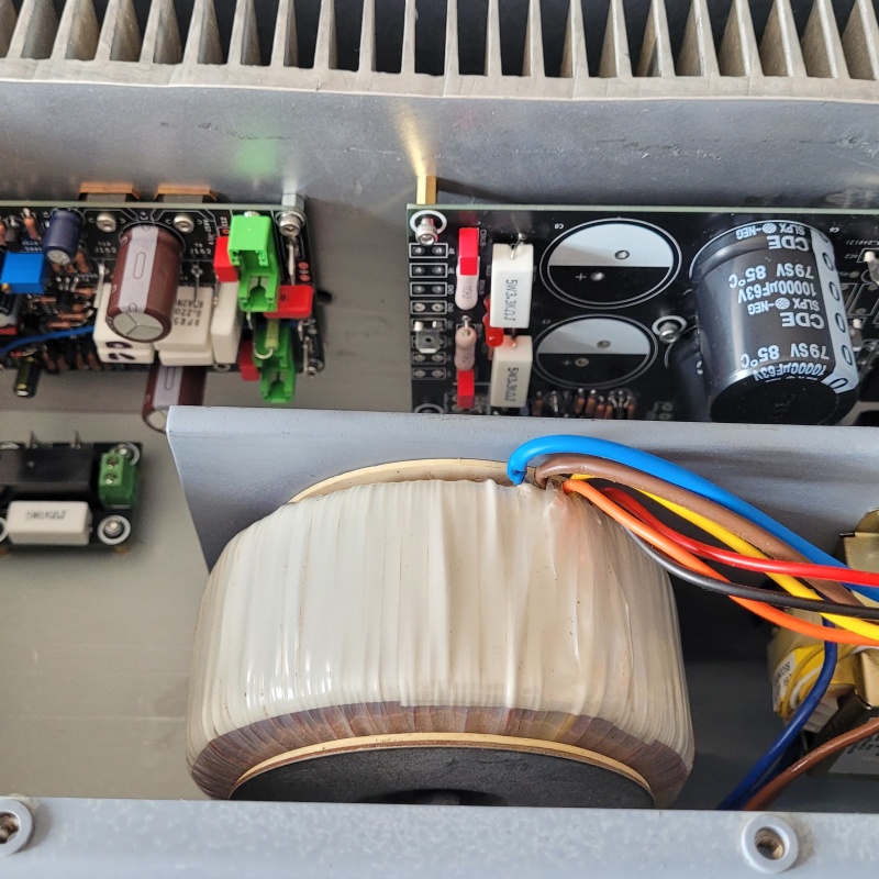
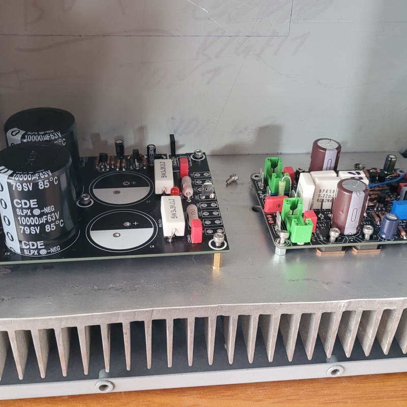
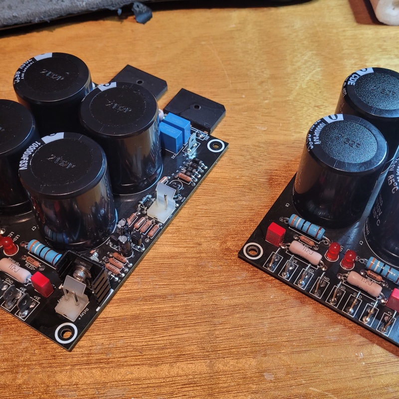
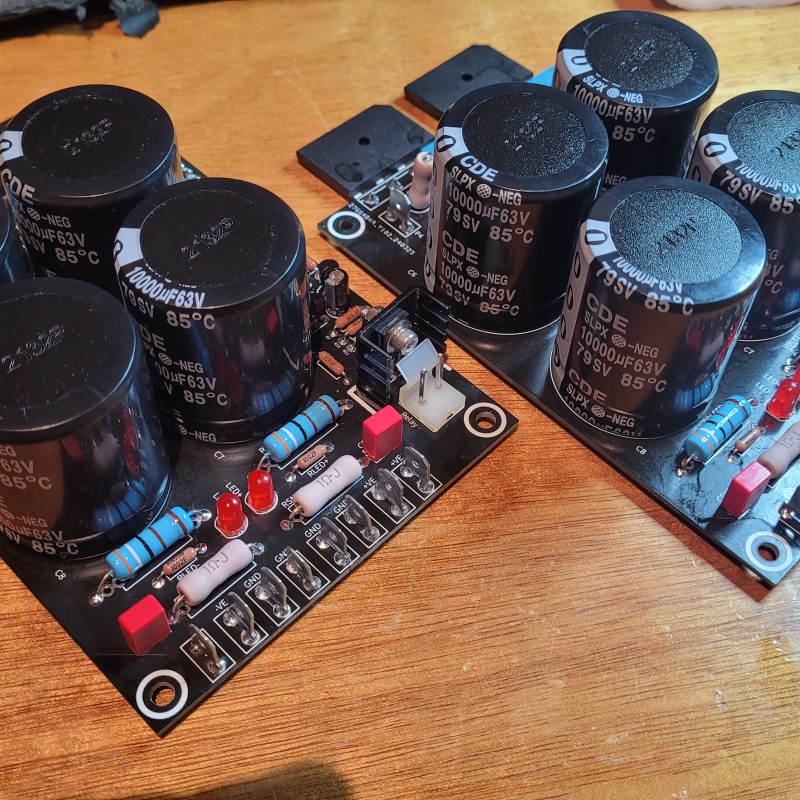
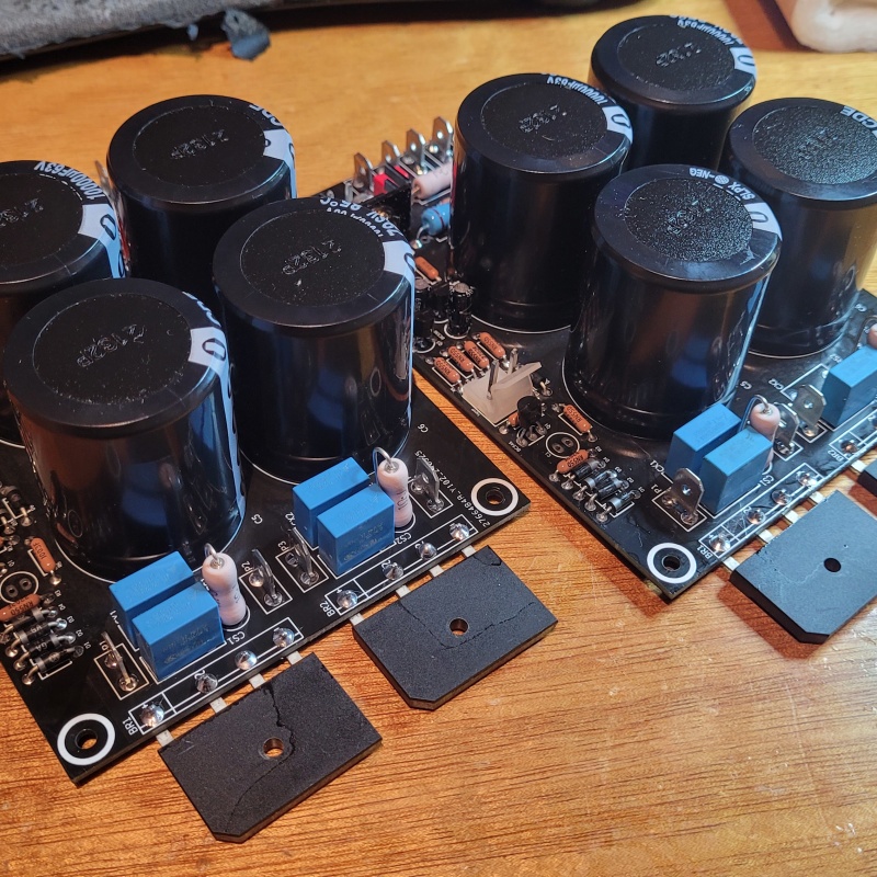
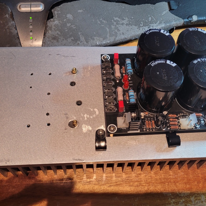
G'day Guys, I've been busy beavering away at this project. I took me a week or two but I am (99%) done with drilling and tapping. The last couple I will sort out once I get to the wiring stage as its just P clip mounts for cable tidying. I've had a wee holdup. My power supply with the integrated speaker protection had a rather glaring error. DC goes where the AC is supposed to go and AC goes where the DC is supposed to go. So a fresh order from JLCpcb of updated PSU boards is on the way. I amended my output relay board to include an output Thiel network. 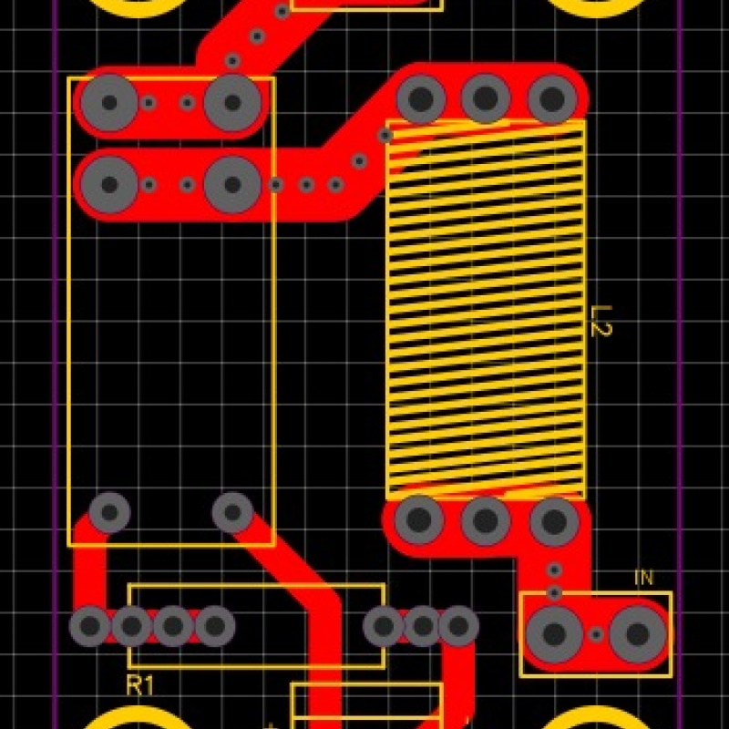 I've left enough space that I should be able to fit a pretty fat coil as required for 5uH. I also amended my ground lift board to better fit a vertical mount 10w 10R resistor. The previous version was about 5mm short. I had a bit of fun with broken taps in my heatsinks. Something to do with being lazy and using a drill.... One particularly nasty one required drilling a hole either side of the tap to get the broken bit out. Exhibit A: 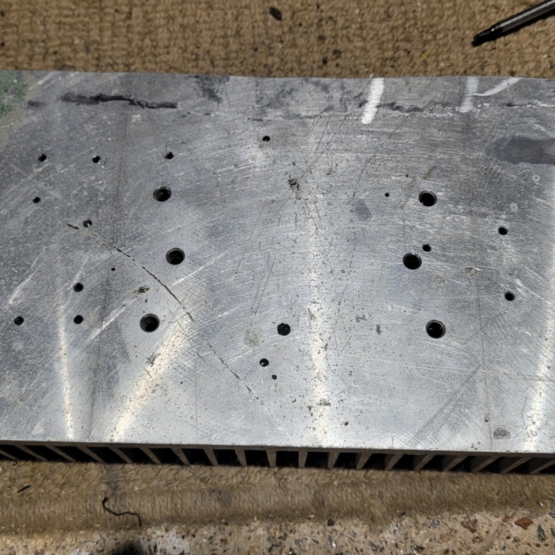 Spot the boo boo. I've fixed up the wound with some JB weld. I will be interested to see how it goes in the long run with the different thermal expansion coefficients. There was a few other mistakes that required the same treatment so this will be a good experiment in repairing heatsink booboos. Luckily the most important holes that hold down the mosfets had no issues. The rest are just holding standoffs to mount the pcbs so if a failure results it won't be a huge issue to find a work around. Once I started just tapping by hand I had no further issues. Whodathunk? Here's a test fit of the completed board mounts. Things are pretty tight at the front of the chassis but I have some good ideas on how to work around here. 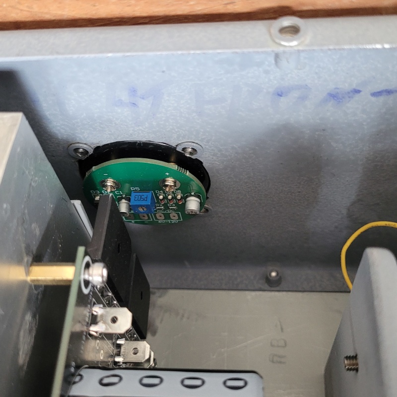 Here's a test fit of the properly tapped and mounted transformer brackets:
When I designed my PSU I was planning to mount the rectifiers directly to the heatsink. However I didn't account for the orientation of the rectifiers. The flat side ended up on the up side. So my solution was to buy some 10x15mm solid aluminium bar from ali express. Nobody local wanted to sell me less than 1.8m. Aliex was something like $6 including shipping for 250mm. After cutting and a bit of sanding I got this: 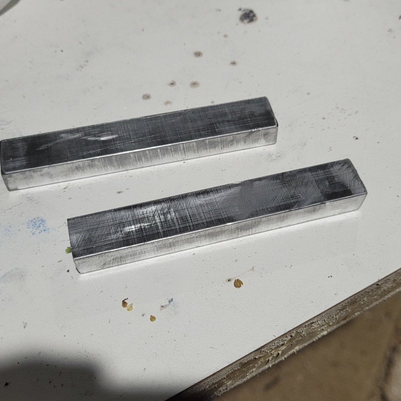 Add some M3 holes for the recitifiers and some holes to go into some m4 holes in the heatsink and voila: 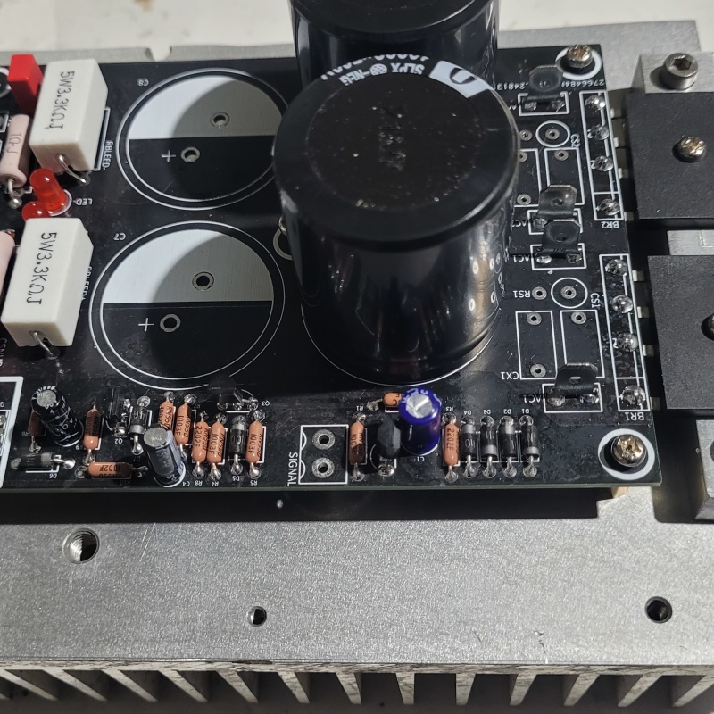 The PSU board was uncompleted for testing. It was at a stage where I could test the speaker protection circuit. However luckily I noticed the error before powering up. For now it a useful template to work around while I wait for the replacement boards. With the heatsinks mostly dealt with. It was time for the next round of gross hole drilling. 154 holes each for the main ventilation under the heatsinks. First to 3.5mm 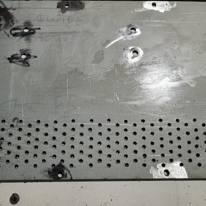 Then to 6mm with the step drill: 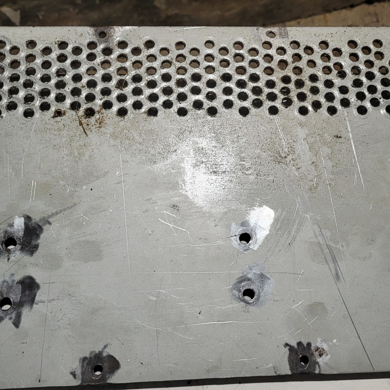 Can anybody spot the hole that somehow went wildly off centre? I wasn't to fastidious with the hole centre accuracy on this set of holes as they are underneath. B surface and all that. I am going to take the holes out to 7mm as I still have a bit of meat to work with. Once I get this done I will remount the heatsinks etc and see how it looks. I think I will want to add more holes for increased airflow. However I need to figure out the placement of the output relay board before I go making holes all over the place. That's it for now.
|
Post by sadface on Apr 16, 2024 22:17:18 GMT 12
G'day Guys,
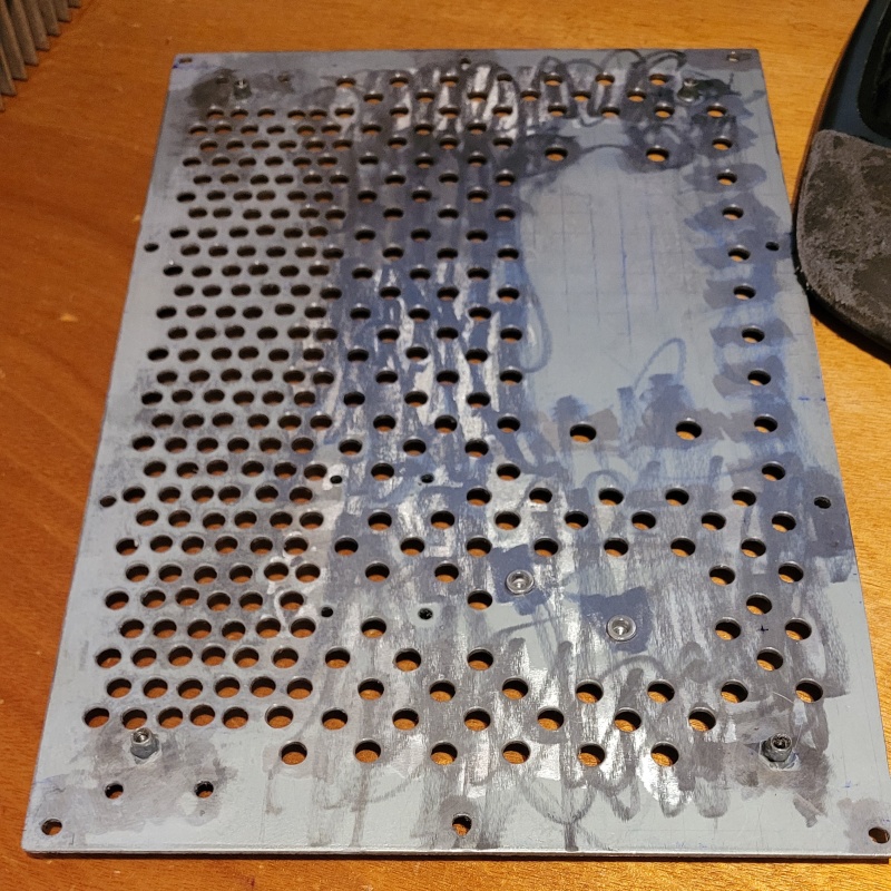
I have finished drilling the vent holes on the bottom side of the.
I think these 2 must have 20 hours of drilling and deburring between them.
First pass to 3.5mm of the 2nd set of vent holes:
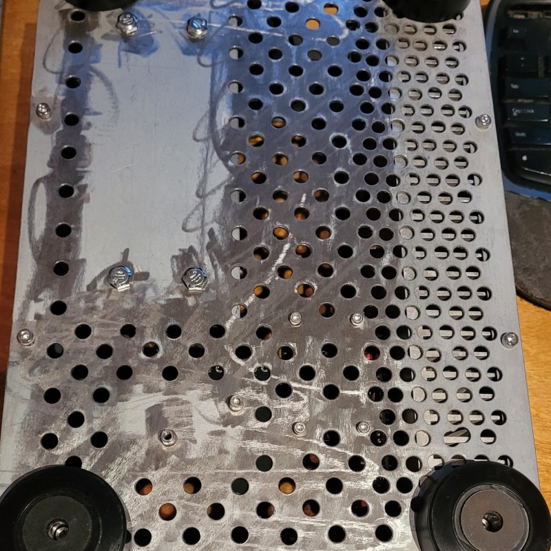
The finished set of vent holes drilled out to 7mm and deburred:
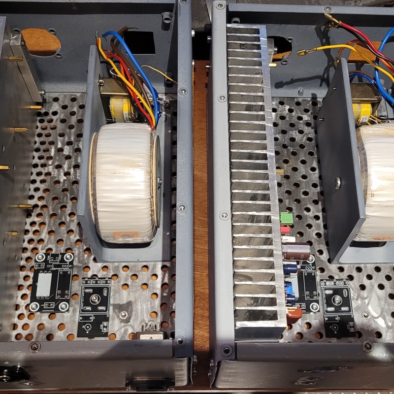
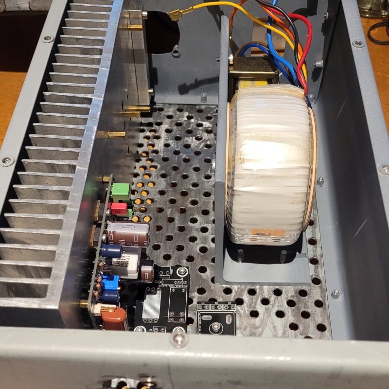
And a wee test fitting session:
A shot from underneath:
I'm very happy with how this has turned out. A lot of work but it looks cool and should provide more than enough ventilation.
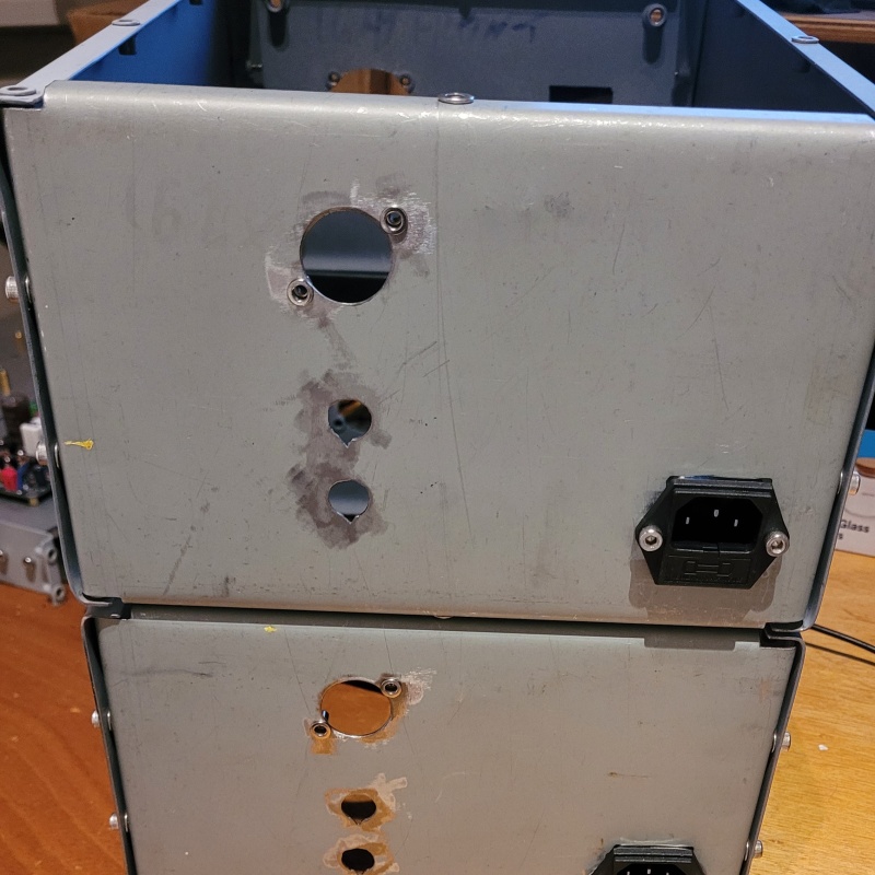
I also finished the placement work for the I/O on the back panel:
The keyways for the speaker jacks were done with a small file. A little bit rough looking but they fit snuggly. I've gone with the Neutrik NFD style rca sockets for this build. I think they look cooler and are easier to work with the regular rca sockets. I tried some ali express knockoffs but I wasn't happy with the quality of actual rca sockets so I replaced them with some genuine neutrik ones.
I'm debating making some more copper plaques for the power requirements and fuse spec like I did on my last tube preamp.
Next up is to place more rivet nuts in the base plates for cable tidying and then these should be ready for a coat of primer.
|
Post by colinf on Apr 17, 2024 6:35:09 GMT 12
Coming along nicely! I did spot the hole position error….I’ve done this before too, easy to do. The magnetic field of a toroidal transformer is generally more concentrated in a plane with the centre hole, so hope the other channel amp board doesn’t pick it up and hum slightly.
AMR-iFi R&D
|
Post by sadface on Apr 17, 2024 20:49:36 GMT 12
Would the mild steel sheet metal chassis not provide shielding for that?
|
Post by colinf on Apr 20, 2024 23:40:07 GMT 12
A definite maybe!
AMR-iFi R&D
|
Post by sadface on Apr 27, 2024 21:36:55 GMT 12
Well this is poos!
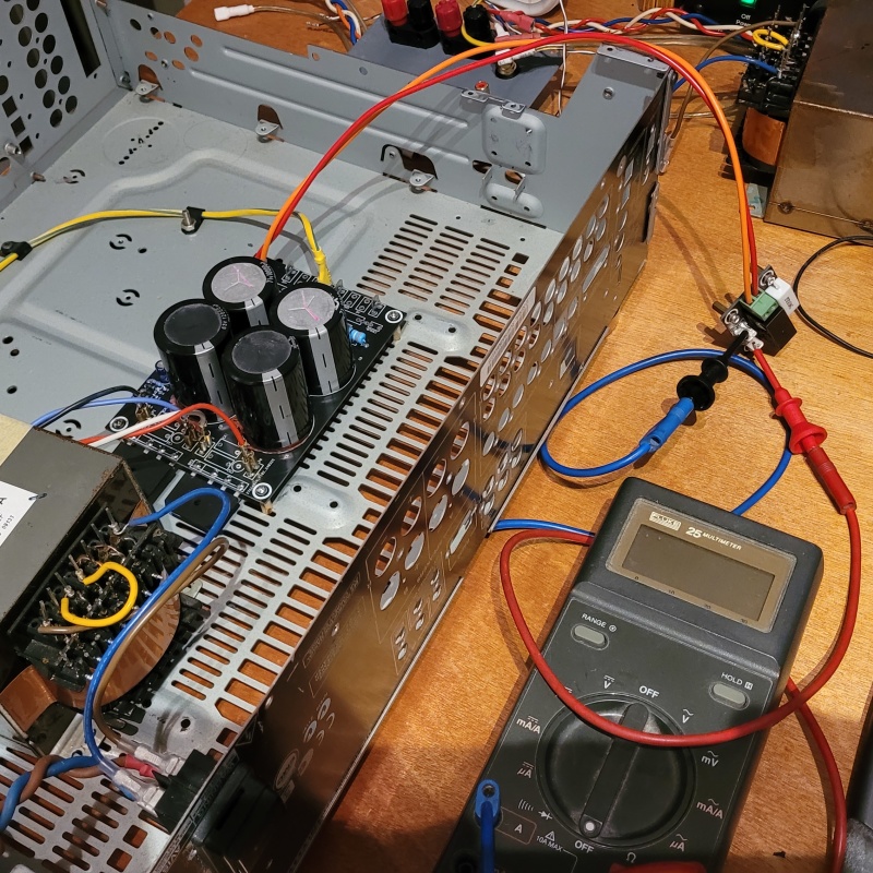
I was all ready to start doing some testing. I've soldered up a test PSU to test my latest PSU design with salvaged parts before I commit good new parts.
I wouldn't let these nasty Samyoung capacitors anywhere near a proper build, but their useful for testing.
This PSU has the speaker protection integarted into the PSU board to cut down on annoying wiring so I want to make sure the circuit works properly before going any further on the build.
And here is the testing rig all ready to go.
And then....... Nothing.
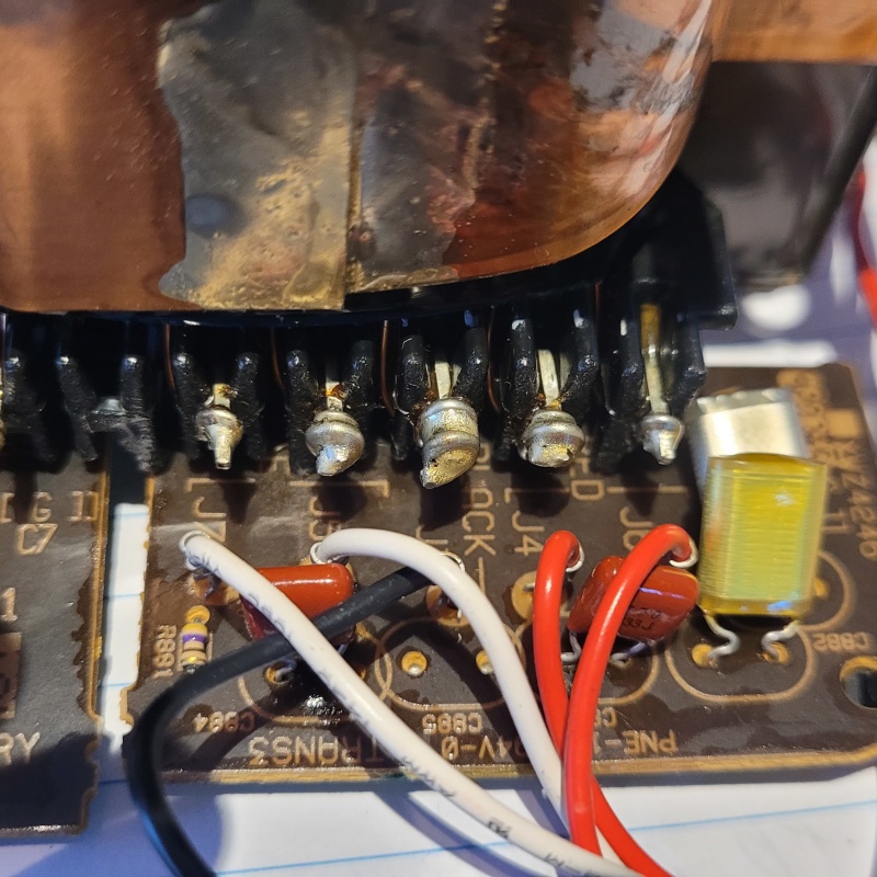
It turns out that one of the transformers I purchased off trademe some time back has a faulty primary. No continuity across the brown and blue wires. So this puts me in a bind. I've designed this build around this pair of transformers. I guess I am lucky I picked the faulty transformer to test with and discovered this now and not later on.
Repairing the primary is probably outside my capabilities as I doubt I could nicely rewind everything with the appropriate tension etc. Having it repaired is, I assume even more expensive than buying a new one.
Which brings me to changing the power transformer. I do have a pair of 225VA, 2x25VAC transformers which I could use with a change to a R27 to something like 6.8k to keep the -12vdc at pin 4 of the opamp. This might be my best option right now.
Otherwise I could have a look at my stash of salvaged power transformers. The difficulty with my salvaged power transformer selection is that they are all EI core transformers with centre tapped secondaries. My power supply design is based on dual secondaries. I might have some which have the secondaries that are exposed in such a way I can separate the centre tap. This might be a workable solution.
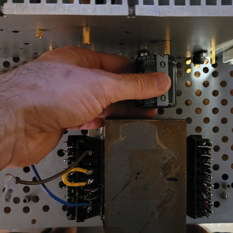
The question is whether they would fit inside the chassis, almost certainly not on the transformer bracket. However given they are home theatre amp transformers they would have an extra secondary to power the lamp on the VU meters and remove the need for the auxiliary power transformers.
I have much to think about.....
|
Post by colinf on Apr 28, 2024 19:41:18 GMT 12
That’s no good for the transformer. It’s quite fiddly to repair a toroidal - just get another one if you can, unless you can get to the break in or near the lead out wires. TL071 only uses about 1.5mA supply current, so 10k might still work with the lowered power supply rails.
AMR-iFi R&D
|
Post by sadface on Apr 28, 2024 20:32:17 GMT 12
Well. It pains me to admit this mistake. After destroying the power transformer I discovered It was not faulty at all.
I was simply very stupid.
The leads are magnet wire and not the normal stranded stuff one gets with more toroidal transformers.
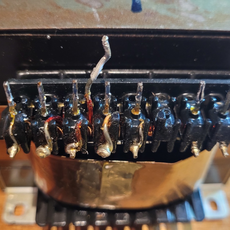
The smart among you can see where this is going. I had simply failed to remove the enamel from the primary wires. The secondaries had obviously had this done by the previous owner of the transformers. Same with the primary on the 2nd one. This one however did not.
After working my way to the primary winding I could see no obvious damage and no thermal fuse. So I thought gee I wonder.....
Embarrassing mistake is embarrassing. Not to mention expensive: destroying a $300 transformer I can't afford to replay.
It will also cost me some time to rejig things to fit my replacement transformer options.
Sigh.
At least I now have a good stash of magnet wire should I need it.....
|
Post by Citroen on Apr 28, 2024 21:32:17 GMT 12
😒
|
Post by sadface on May 5, 2024 19:39:10 GMT 12
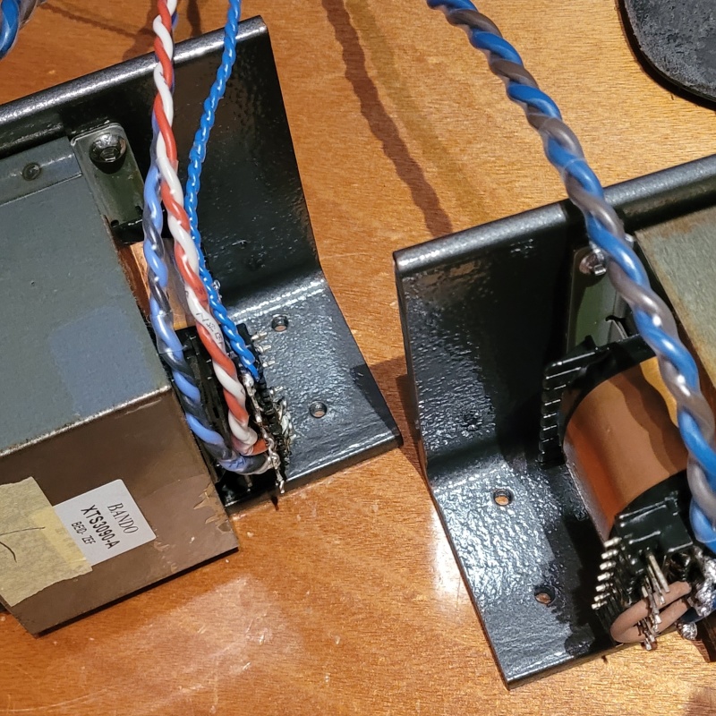
G'day Guys, I've made some good progress on the replacement power transformers. 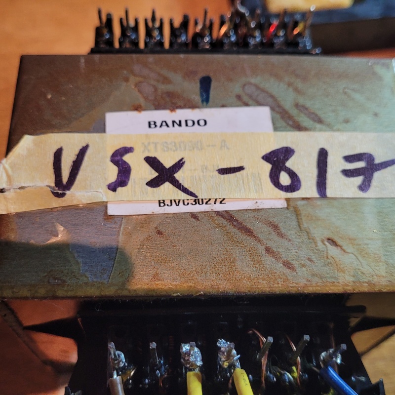 I found a pair of power transformers in my stash of salvaged parts from a Pionner VSX-515 and a VSX 817 which have the same Bando model number. 300w or 420VA according to the service manuals. 28VAC unloaded. There is minor differences in the other low voltage secondaries between the 2 but nothing important. These are the type of transformers with the little pin termination thingies that allow a pcb to be mounted directly to the transformer.
I managed to separate the centre tapped secondary for the B+ to create to separate secondaries suitable for my power supply design with its dual bridges.
I soldered on some nice 18awg silicon insulated wire leads that I salvaged from some coffee machine or another.
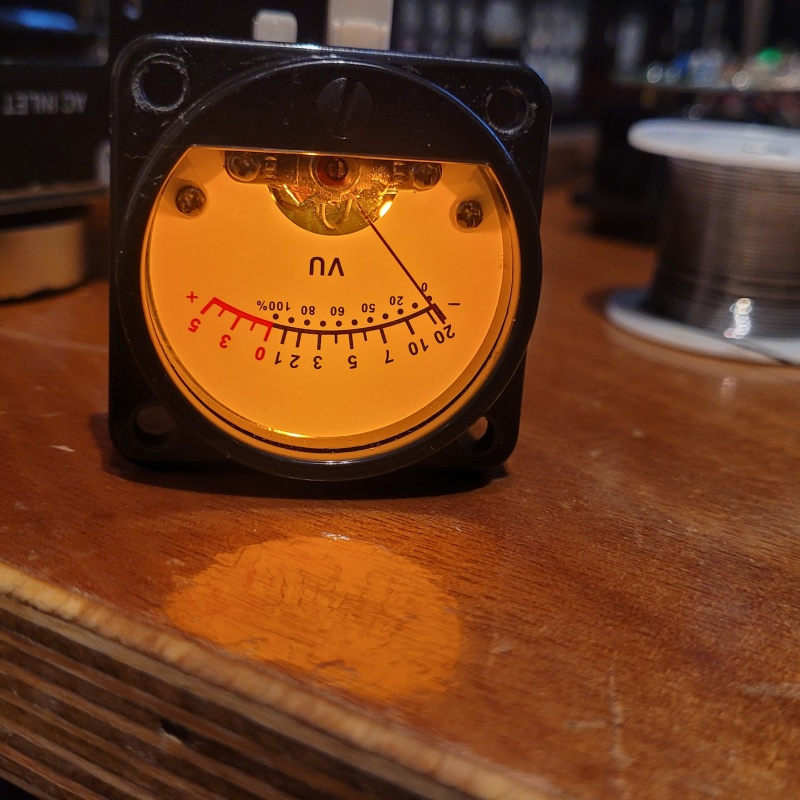
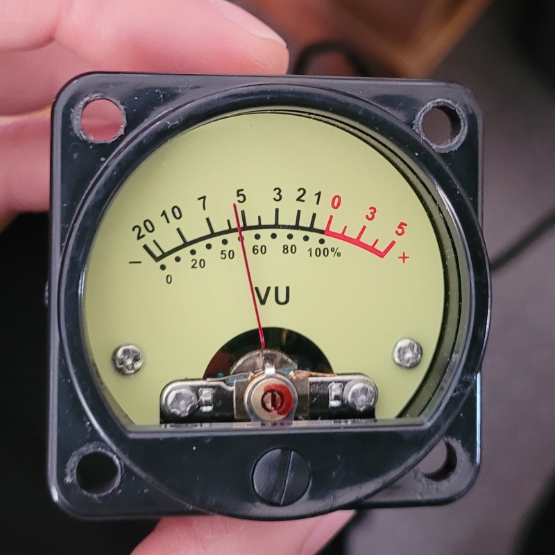
PSU test went well. No sparks or magic smoke. Indicator leds light up properly. The rails are lower than I was hoping but good enough. I am getting +37.3Vdc and -37.5vdc. My guess is that the difference is in the small load on the +ve rail from the speaker protection. I will be interested to see if this changes at all when I build the proper PSUs with their better main filter caps and extra snubbers etc. I hypothesize that with the (probably) lower ESR Cornell Dubelier filter caps the rails will slightly higher. Speaker protection works perfectly. Turns on after 1s and off immediately upon power off. When exposed to the power rails through a 100k resistor the dc detection triggers properly. After playing with the RC constant on the speaker protection I now have a circa 3.5second delay on power up. I also tested the VU meters. They were sold as yellow but to me it looks more orange once the lamps are on. I love the look of it anyway. I also hooked it up to a sig gen to test the meters work and see what the calibration looks like. With a 9v sine wave it shows 55% power. If I am doing my maths right that means 100% is 16v which seems a bit low given 50w into 8R is 28.3v . I will test this more once I have the amps up and running and can run a larger signal through the meter. Not the end of the world if it is as this would mean the meter would move more at lower volumes where the amp is likely to spend most of its life. However I need to assess the possibly the meter would get damaged the amp was ever driven to full power. Right now I am building the proper power supplies so that I can test them and finalise the transformer lead lengths and dress the wires etc. It will also show me how much room I have to move my power transformers bracket to accommodate the larger EI core transformer. Mounted bottom down puts the transformers a bit close to the caps in the PSU for my liking.
I plan to keep the transformers mounted on their side to take advantage of the extra vertical space available and save some horizontal space. I am hatching a master plan to epoxy pot the transformers. Mainly because I don't like the open terminations on these transformers but I also see other advantages for vibration damping and protection from the elements. Most importantly I think they will look cooler.
|
Post by colinf on May 7, 2024 6:33:49 GMT 12
The meter reads average voltage. 20Vrms is 50W into 8 ohms (28.3V is the peak). The meter would show 100% at 16.4Vrms, so you’d probably need a resistor in series with it to get it to read 100% at 20Vrms.
AMR-iFi R&D
|
Post by sadface on May 7, 2024 21:21:37 GMT 12
The meter reads average voltage. 20Vrms is 50W into 8 ohms (28.3V is the peak). The meter would show 100% at 16.4Vrms, so you’d probably need a resistor in series with it to get it to read 100% at 20Vrms. Ah yes of course. Peak vs RMS strikes me again!
Am I correct that at a reading of +5Vu the meter would be at 150% which would be at 24.6Vrms.
24.6Vrms is 34.7Vpeak which is pretty close to the rails and is probably about where clipping would be expected?
|
Post by colinf on May 9, 2024 18:55:20 GMT 12
It might be good to work out what the actual output power of the amp is, so you can calibrate 100% indication to 1% THD. The meter would read more than that with a distorted (clipped) sinewave as the rms power still increases, despite frying your tweeters. It looks like 50% FSD (full scale deflection) is just under 70% on the lower scale, making 140% the maximum.
AMR-iFi R&D
|
Post by sadface on May 18, 2024 22:00:35 GMT 12
I've been working away still.
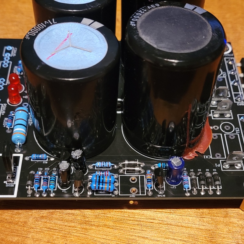
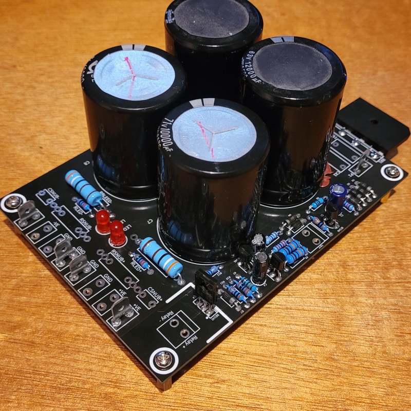
I built and tested the actual PSU boards now that the PCB has been verified. Since these photos, the remaining capacitors arrived and the PSU's passed testing.
The rails were slightly higher, +/- 37.5vdc but that could just be mains variation rather than the lower ESR in the caps.
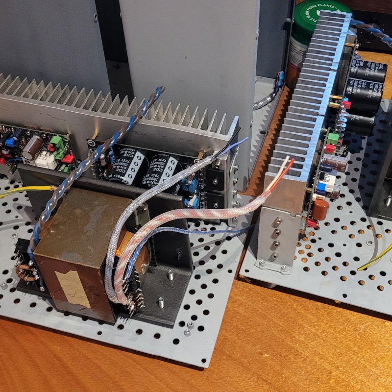
I've also done most of the work on dressing the leads for the power transformers: Everything all nicely heatshrunk and covered in PTFE braid.
Notice the painting sample on the brackets. This time I'm going with Black hammered rustoleum. It's perhaps more of a dark grey than a black but very attractive nonetheless.
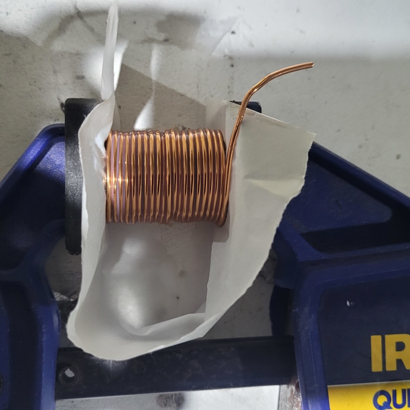
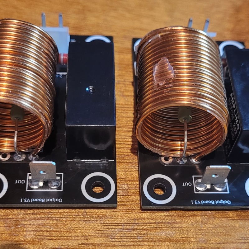
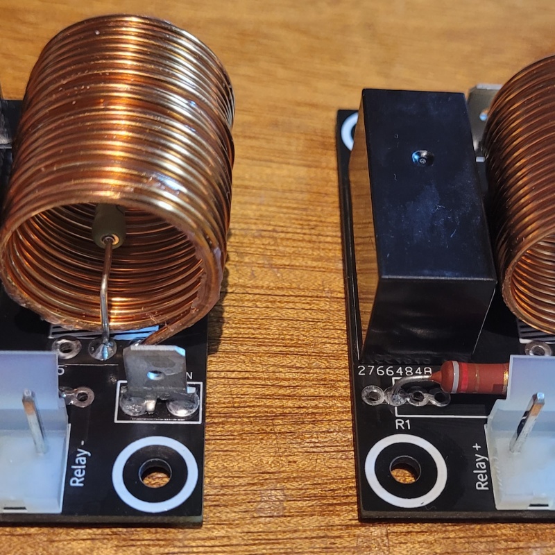
This evening I managed to wind a nice set of coils on my second attempt for the Thiel network at the output: Drying out after a dip in the varnish can. A bit of baking paper to protect the clamp jaws from the varnish and a light clamp to hold the coil tight.
Much progress. With the coils coiled I can solder them to the boards and start the wiring for the In/out side of things and then it should all be ready for testing.
|
Post by sadface on Jun 2, 2024 21:57:14 GMT 12
It verks! Noise!
It's been a busy couple of weeks to get some noise out of some test speakers.
I had a bit of extra time time this last week as I did something to my right Achilles tendon so I couldn't train all week.
Output boards all soldered up: These boards integrate the output Thiel network and protection relay.
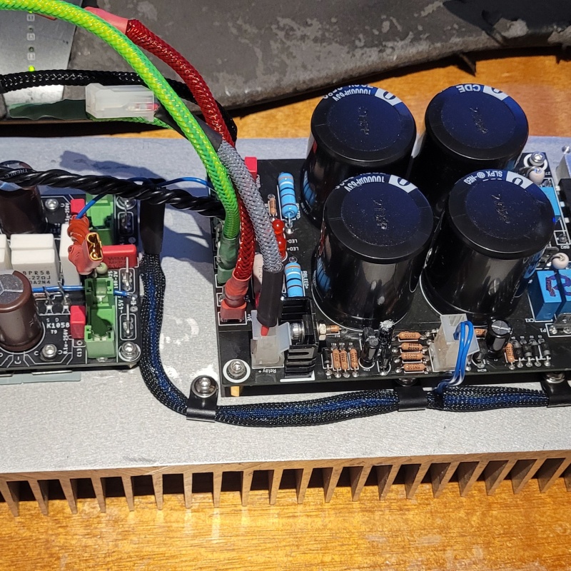
Amp board and PSU mounted up to the heatsink and partially wired up.
It always amazes me how long it takes to get the wiring all neatly cut, twisted, terminated, braided etc.
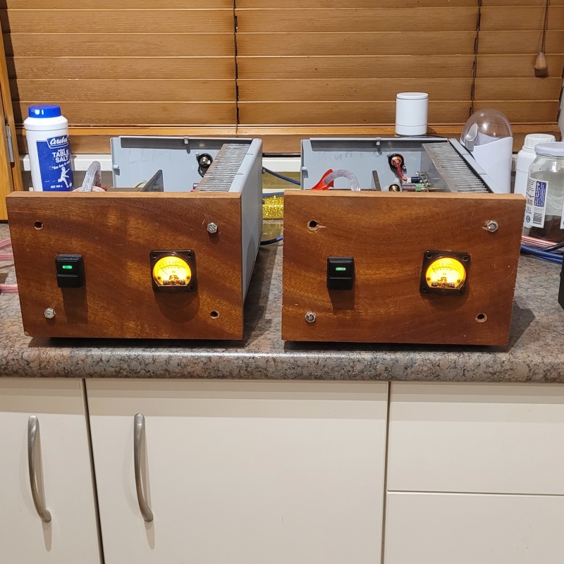
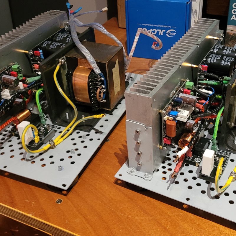
Here's the pair almost ready to go:
Right channel wired up ready for power:
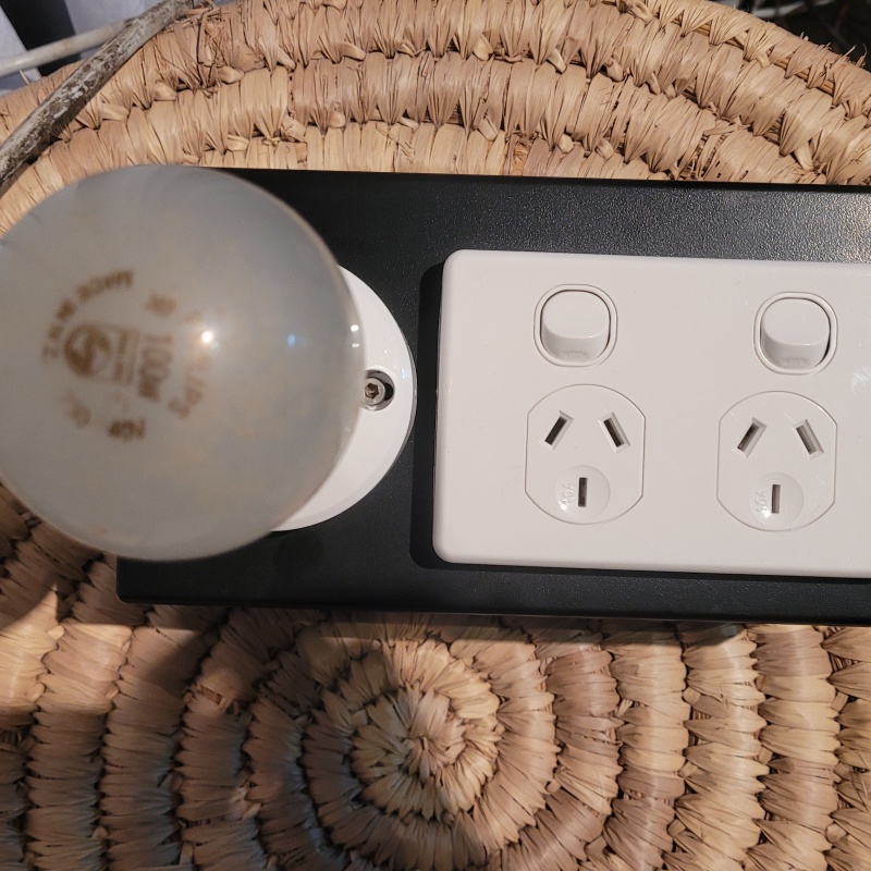
I decided it was about time I make a dim bulb tester. A jaycar jiffy box and some parts from my stash: Notice the NZ made bulb. I wonder how old that is. Do we still make such things in NZ?
Startup went without a hitch. No magic smoke or blown fuses.
Voltages at key nodes in the circuit were as they should be. DC offset was 0.2mV on the left channel and 0.6mV on the right channel.
Biasing was nice and smooth. The bias was set to 100mA via 44mV measured from drain to drain. Across all 4 combinations of pairs and the voltages varied up to 2mV so the lowest pair was set at 44mV.
After biasing it was time for test speakers and noise.
Now that I know they work basically as expected, tomorrow night I will get out my scope and sig gen and start torturing them to see if they scream.
|
Post by colinf on Jun 7, 2024 18:04:10 GMT 12
Good to see them coming along. I tend to use a variac to ramp voltage up slowly. Class AB mosfet distortion gets lower the more bias you give them. Above 200mA each mosfet (for the K1058/J162 pair) the tempco becomes positive, necessitating temperature compensated bias. This circuit doesn’t have temperature compensation, but the mosfets are in the feedback loop of the driver transistors, which then dominate the bias setting with temperature.
AMR-iFi R&D
|

