Post by sadface on Nov 5, 2022 22:08:19 GMT 12
G'day Guys,
In the works is a Rod Elliot P3A 60w class AB into 8 ohm.
This one has been brewing for a few years in the background. Collecting parts etc
It will be my first foray into discrete class AB.
I know, I know. I have to many projects but hey a man needs to keep himself busy. Idle hands and devil's work and all that.
So far the amp boards themselves (purchase from Rod) are half populated with the resistors. I'm waiting on the last few parts which will hopefully arrive from Mouser on Monday (according to DHL).
Since I am limited on 'noise time' for my chassis build on my tube pre. This project has been ticking along nicely in recent weeks.
So much so that I can introduce the power supply board!
     
Over engineered as is my usual style. 2x 15000uF per rail. This should be more than enough for 2 channels of 60w
Dual rectifiers with a CRC snubber across each secondary. Nothing too outrageous here, just generic 0.1uF/ 1R & 0.1uF. I haven't bothered to measure or calculate the exact value as I know this should work pretty darn well to dampen transformer ringing with these generic values.
Generic 0.1uF/1R Snubbers on the outputs. All the in/out spade connections I could possible need. 300VA power transformer
I will also apply some copper sheet to the rectifiers to act as heatsinking.
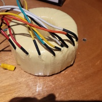
The power transformer is currently waiting on some 600v wire so that I can rewire the secondary from a centre tap to dual secondaries.
All going as things might, this amp could plausibly be thrown into a test chassis and making noises over the new years holiday.
|
Post by colinf on Nov 6, 2022 6:39:22 GMT 12
Good luck with the build. Use an E-152 constant current diode in place of R8. Also connect R2 directly to the base of Q1 😉
AMR-iFi R&D
|
Post by sadface on Nov 6, 2022 10:45:27 GMT 12
Thanks for the suggestions. Have you built one of these?
I've already populated r8 and r2 on Rod's boards.
However if all goes well I will build another set as monoblocks so perhaps I can make those changes on the 2nd time round.
|
Rod Elliot P3A Nov 7, 2022 20:23:08 GMT 12
- Edited Nov 7, 2022 20:26:47 GMT 12 by RdM
Post by RdM on Nov 7, 2022 20:23:08 GMT 12
What transistors did you order? How large are the heatsinks recommended to be? Comparable to an LM3886 amp? I have an old Technics silver face receiver, SA-T670, that some previous idiot had removed the original power stage from, and replaced with an early Jaycar set, itself failed since, didn't get good reviews, surpassed since. The heatsinks are still there. I'm wondering what sort of power amp stage could repurpose it. I don't know what the preamp drive is. How to match up a new power stage to an existing preamp stage? Else to rebuild to original? But maybe more modern is indeed better. So why not? How?
~ RdM
|
Post by colinf on Nov 10, 2022 8:26:51 GMT 12
Thanks for the suggestions. Have you built one of these? I've already populated r8 and r2 on Rod's boards. However if all goes well I will build another set as monoblocks so perhaps I can make those changes on the 2nd time round. Not this exact kit but have lots of fiddling experience with these straight-forward circuits…. The PSRR of the constant current source (CCS) diff tail isn’t that high with an LED reference, and with class B switching spikes on the negative rail from the output stage, and single-ended VAS (voltage amplifier stage ie. the 2nd gain stage) with no current mirror for cancellation, high frequency performance is quite power supply quality-dependent. So adding a CC diode to the diff tail CCS helps. Also making the DC impedance at Q1 base the same as the feedback network allows the input stage to be biased more accurately for better error subtraction. As the long-tailed pair of transistors on the input stage has no emitter degeneration resistors, the DC bias should be spot-on for lowest distortion. The CCS should also be set spot-on for this reason. The VAS generates a bit of 2nd harmonic distortion, which can also modulate the DC bias of the input stage while playing music - no quick fix for this without adding DC servos around the driver stage, etc. But don’t worry too much about performance stuff, these circuits are fun to build, and you can tweak the power supply to make it sound how you like!
AMR-iFi R&D
|
Post by sadface on Nov 10, 2022 19:50:21 GMT 12
What transistors did you order? How large are the heatsinks recommended to be? Comparable to an LM3886 amp? I have an old Technics silver face receiver, SA-T670, that some previous idiot had removed the original power stage from, and replaced with an early Jaycar set, itself failed since, didn't get good reviews, surpassed since. The heatsinks are still there. I'm wondering what sort of power amp stage could repurpose it. I don't know what the preamp drive is. How to match up a new power stage to an existing preamp stage? Else to rebuild to original? But maybe more modern is indeed better. So why not? How?
~ RdM
I am using: BC546 for Q1,Q2,Q3,Q9 KSA1220 for Q4 & Q6 KSC2690 for Q5 2SA1943 for Q7 2SC5200 for Q8
KSA1220 & KSC2690 are supposedly a great driver combination for the 1943/5200 I also have some salvaged 2SA1302 & 2SC3281 which are supposedly the best sounding outputs but are obsolete so these have to be salvaged. Faulty 90s amps are good candidates.
I plan to use these monoblocks for version 2.0
Silver Mica capacitors for C2, C4, C6 100pF caps. Supposedly the best option in this part of the circuit. Standard MKT for the 100nF decoupling caps 1uF Panasonic polypropylene for the input coupling caps. I would have preferred a larger value at the input for the low pass filter. However, this was the largest value I could fit onto the pcb without doing silly things with the leads/ placement.
I might well do my own pcbs the second time round. There are some obvious improvements that could be made to Rod's pcb design the least of which would be space for proper input coupling caps.
|
Post by sadface on Nov 10, 2022 20:44:02 GMT 12
What transistors did you order? How large are the heatsinks recommended to be? Comparable to an LM3886 amp? I have an old Technics silver face receiver, SA-T670, that some previous idiot had removed the original power stage from, and replaced with an early Jaycar set, itself failed since, didn't get good reviews, surpassed since. The heatsinks are still there. I'm wondering what sort of power amp stage could repurpose it. I don't know what the preamp drive is. How to match up a new power stage to an existing preamp stage? Else to rebuild to original? But maybe more modern is indeed better. So why not? How?
~ RdM
The minimum heatsink required for both channels is 0.5c/w at least with a +/- 35vdc supply.
With lower voltage one could perhaps get away with a smaller heatsink.
Bigger would generally be better of course.
|
Post by sadface on Nov 10, 2022 21:08:08 GMT 12
Lousy weather makes me not want to brave the rain to get to the basement for drilling of my chassis project.
For this reason, progress has been pretty good.
I've been taking my time:
Making sure the right components go in the rights places.
Dressing leads and solder pads, keeping the pcb clean.
There's only a few bits to go: Driver transistors, bias transistors, outputs and the electrolytics.
I spent a wee bit of time with the drivers tonight making sure the pinouts are correct. Turns out they are.
|
Post by sadface on Nov 13, 2022 21:04:58 GMT 12
We're getting close to the home stretch.
These have been sitting in my stash waiting for a few years now. I finally get to play with them!
I've had a minor setback otherwise, I only have 150uF electrolytics on hand with an 8mm diameter and 3.5mm pitch. Perfect for supply rail decoupling but I dont want to change the value from 100uf for C3 and C5.
Element 14 too the rescue albeit its probably going to be over a week before they arrive.
I'll solder up these output transistors while I wait and then perhaps start work on speaker protection.
I also found a heatsink in my stash that should be appropriate for initial testing. Its from a sherwood RD6502 AV reciever.
It has the exact 1.5" pitch I need to mount the output transistors. I've made a guesstimate of its thermal performance based on its mass. Crude I know but oh well.
By my guesstimate its probably a bit small. However it is from an amp with 330 power consumption and 2x 100w continuous for the front speakers so maybe it would be enough. I have some larger heatsinks which I might use in the final build anyway. This one is simply convenient for testing as I don't have to drill and tap.
|
Post by RdM on Nov 13, 2022 21:20:10 GMT 12
I fear that I haven't understood the 0.x? °c/w ratings for heat sinks yet, and how to relate them to physical size, mass, surface area with number of fins, etc. I know Rod Elliot had a page on that, I should find and re-read. I'm tempted to take a punt, but know I should try to understand and measure.
At the least I'll take photos and some measurements, see if I can plug them in somewhere and understand better. Thanks! ;=})
|
Post by sadface on Nov 14, 2022 19:59:29 GMT 12
I fear that I haven't understood the 0.x? °c/w ratings for heat sinks yet, and how to relate them to physical size, mass, surface area with number of fins, etc. I know Rod Elliot had a page on that, I should find and re-read. I'm tempted to take a punt, but know I should try to understand and measure.
At the least I'll take photos and some measurements, see if I can plug them in somewhere and understand better. Thanks! ;=})
To do it properly requires a bit of calculation or measurement. 
Based on the specs and the size of that heatsink in the photo, I think the heatsink is a bit undersized.
Tricky shape on that heatsink to work around too.
Depending on the voltages out of that power transformer maybe a chipamp might be easier. However I would guess that power transformer is putting out something annoying like 30-35vac which would be too high for an LM3886.
|
Post by RdM on Nov 15, 2022 18:36:31 GMT 12
Thanks for that!
I'll take a pic of the heatsinks in my above dud converted power section receiver. No free service manual for the original, but available for $.
Cheers!
|
Post by sadface on Nov 27, 2022 20:56:01 GMT 12
G'day Guys,
Parts finally arrived to finish off these boards.
Last night I had some time to do the work.
 Output transistors mounted (cropped image to hide Rod's layout IP) 
And here is the boards with a test fit on the test heatsink.
Next up is finishing up the secondaries on the power transformer however the wire hasn't arrived yet.
In the mean time I might start sorting out a suitable testing chassis.
|
Post by RdM on Nov 28, 2022 19:00:01 GMT 12
I just wish you could choose larger thumbnails, the max size, when uploading your progress diary images. Is there an option to choose thumbnail size? The default is too tiny. Make it a good size in the thread, so we don't have to click through hoops to get the full size image so much? The work looks great!
|
Post by sadface on Nov 28, 2022 20:27:41 GMT 12
No thumbnail options that I can find sadly.
|
Post by RdM on Nov 28, 2022 20:40:19 GMT 12
You can post without an account, but get more options if you sign up for a free one. Go through each step, choose favourable options and 800 x 800 resized thumbnail. If you sign up free you can create galleries, folders, you can set default preferences, and it can remember you.
Best wishes! ~
|
Post by RdM on Nov 28, 2022 21:11:23 GMT 12
For instance, even as a guest, you can change the defaults from 100x100pix &etc to something more like And then when the result is loaded, you choose / copy the BB code on the top right. Then paste that in to your reply. Thus:
But if you sign up - and actually I've posted my last 10-12 as a guest, a new PC instance, haven't copied the login, you have total control over all your uploads.
The best I've found so far. No pushy ads or extraneous images;- just your own.
Best! ;=})
|
Post by rmc001 on Nov 30, 2022 11:54:36 GMT 12
Tapatalk app has thumbnail size options and ability to zoom. (Also click to end of thread which I find handy compared to viewing in Chrome.)
|
Post by sadface on Dec 6, 2022 20:23:59 GMT 12
In a stroke of good luck my test heatsink seems to fit my test chassis like a glove.
Perhaps the Sherwood receiver and this Marantz chassis were made in the same factory. The Marantz heatsink is a bit taller with slightly thicker metal on the fins.
However the mounting points are all identical.
  
More work saved!
I think I will definitely use the larger heatsink that comes with the chassis when I get to the final build.
Its from a Marantz SR5200 which is rated at 310w power consumption and 270w dissipation on the heatsinks (if I am reading things right). That should be plenty for 2x 100w into 4ohm speakers. Not that I am likely to make that much noise any time soon.
Sadly the power transformers on these amps are always to high a voltage for what I am building here. I'm slowly building a stash of power transformers I can't use.
|
Post by sadface on Feb 1, 2023 21:18:51 GMT 12
G'day Guys,
Progress has been slower than expected over the holidays.
My workshop was tied up with a project for She Who Must Be Obeyed, however that project is finally done so I'm back on track.
Bits finally arrived to finish the modification to the power transformer. Here is everything buttoned back up again.
I reused the old clear mylar insulation and the gave it another layer of 3M #56 tape just to make sure the insulation won't fail.
And now I can start thinking about the layout.
Here's a wee teaser!
Also when looking at this thread, none of my old images seem to work so I'm trying imgbox.
|
Post by RdM on Feb 1, 2023 21:33:00 GMT 12
Also when looking at this thread, none of my old images seem to work so I'm trying imgbox.
Congrats!
But next time choose 800x resized for your thumbnails. Join up free, let it remember you, then you have even better control.
A visually disturbing lack of symmetry in that mock layout pic.
|
Post by sadface on Feb 2, 2023 21:21:27 GMT 12
A visually disturbing lack of symmetry in that mock layout pic.
Its hard to do symmetrical with a single psu. 
Its also quite a large chassis for what is currently in there. Not a bad thing in my books though, more distance between the transformer and the signal.
The final form of this should be prettier. For now its a test bed.
|
Member

Post by bwd on Feb 3, 2023 19:44:04 GMT 12
Over engineered as is my usual style. 2x 15000uF per rail. This should be more than enough for 2 channels of 60w
Dual rectifiers with a CRC snubber across each secondary. Nothing too outrageous here, just generic 0.1uF/ 1R & 0.1uF. I haven't bothered to measure or calculate the exact value as I know this should work pretty darn well to dampen transformer ringing with these generic values.
Generic 0.1uF/1R Snubbers on the outputs. All the in/out spade connections I could possible need. 300VA power transformer
I will also apply some copper sheet to the rectifiers to act as heatsinking.
The power transformer is currently waiting on some 600v wire so that I can rewire the secondary from a centre tap to dual secondaries.
All going as things might, this amp could plausibly be thrown into a test chassis and making noises over the new years holiday.
Board looks great! Nice stuff.
Electronics Technician - Pitch & Pixel
|
Post by sadface on Aug 31, 2023 21:01:02 GMT 12
G'day Guys,
With the LM1875 build finished this project got back onto my desk.
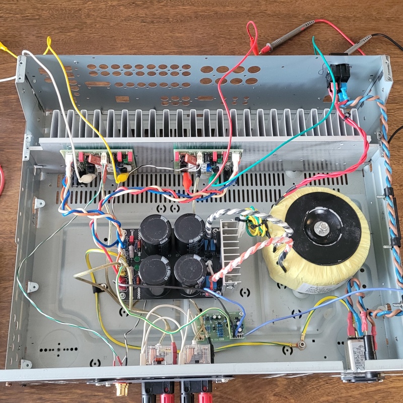
I have wired up the test bed in the Marantz chassis.
I ended up moving to the larger heatsink. I just didn't like the look of the smaller heatsink in the end. I got a set of drill taps like these a while back.
They made short work of tapping the aluminium heatsink. I would highly recommend a set of these. The took all of the chore out of the chore of tapping. Well worth the money.
I also got around to adding the heatsink to the rectifiers on the power supply. I didn't think the process through very well. Due to the proximity of the rectifiers to the filter caps, it would be a huge pain to get in there to fasten the fasteners.
I removed the rectifiers, screwed them on the heatsink and they re-soldered them back onto the board. The heatsink was salvaged from some faulty home theatre receiver or another. Once again, the drill-tap made short work of the tapping job.
I also added some m4 rivet nuts onto the sides of the heatsink. When I get onto the proper build of this amp, I will make some little brackets to keep the heatsink from wobbling around.
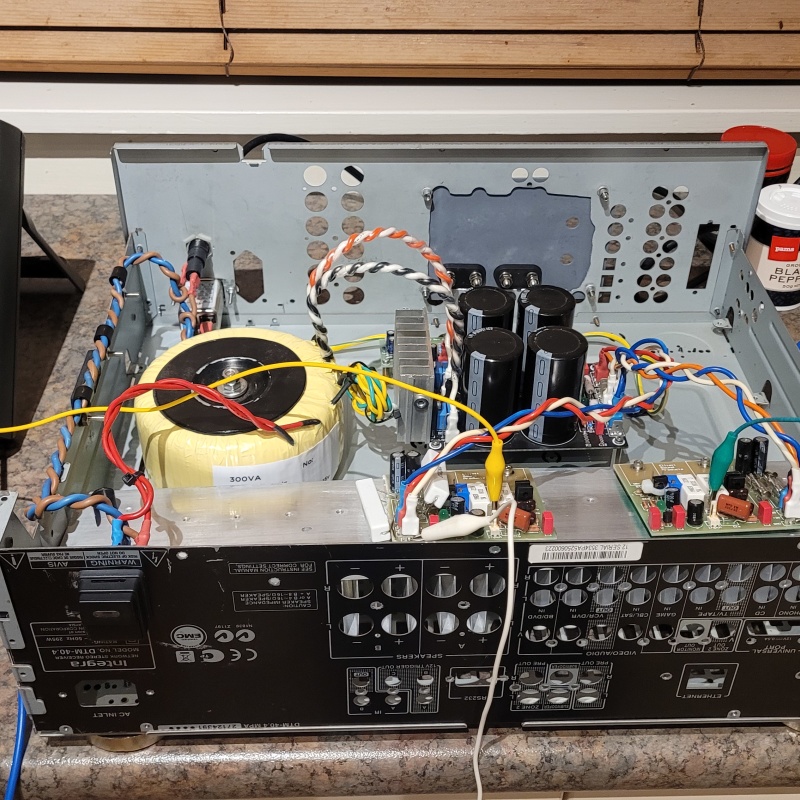
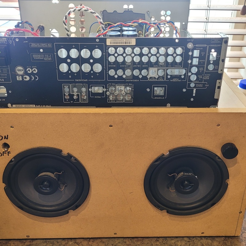
Conveniently I found that the back panel form an Integra DTM 40.4 fit perfectly with the Marantz chassis as a deliciously crude front panel. Perfectly serviceable for the test rig.
I finally ran out of the Jaycar mains cable for the AC side. I tucked into my stash of recycle coffee machine stuff and got some 12AWG 600v stuff from what was probably a Wega Polaris 2 Group coffee machine. 20A rated cable is probably overkill, however it was actually much easier to work with than 10A rated Jaycar stuff. With the Jaycar wire I have to heatshrink it with clear 6mm heatshrink to maintain the twisting of the pair. With the salvaged coffee machine stuff it twists easily and it holds beautifully as you might see in the photo.
Same again with the power switch. I am out of the little illuminated jaycar ones so I've moved onto my stash of coffee machine power switches. This one is a push button type with a lovely heavy clunk. I will be using a few of these as I have a bunch of matching ones for my next series of builds.
And here we are on the kitchen bench after the initial round of testing. No explosions, magic smoke or any other such bad stuff. Next to 0V DC offset.
Tonight I will do some biasing and if all goes well I will connect up a speaker.
|
Post by sadface on Sept 6, 2023 20:37:00 GMT 12
G'day Guys,
Some good progress on this build. No issues with the build so far which is a blessing.
The biasing job went nice and smoothly. I slowly raised the bias to 75mnA over an hour or so. No dramas, nothing ran away, nothing over heated.
The temperature of the pcb directly above the output transistors rose 10 degrees above ambient but the rest of the heatsink stayed at ambient. The driver transistors etc heated up a little bit but only a few degrees.
The next step was to finish the wiring. Input wiring. Output wiring Speaker protection wiring.
Here's the test rig about to fire up, test leads and DMMs rigged up to monitor the bias during testing.
Test rig and test speakers on the kitchen bench.
Everything worked properly, the speaker protection system worked flawlessly.
It triggers properly with power up and down. It also triggers properly when exposed to the positive and negative rails via a 100k resistor
Most importantly, Lily Allen burst forth from the speakers.
So all of the initial tests have now been passed. I am waiting on some chassis mount power resistors to arrive so that I can get out the scope and do some stability testing.
In the mean time, chassis work is well under way.
|
Pundit
 
Post by peter0c on Sept 9, 2023 16:11:08 GMT 12
Slightly off topic but only slightly. I was interested in the current flavour of the month speakers - Heriticy coaxial speakers (NOT the Klipsh Heresy) - which use series crossovers. Rod Elliot wrote and informative paper on parallel v's series crossover in 2003 which has been updated. Here it is. www.sound-au.com/parallel-series.htm
|
Post by colinf on Sept 13, 2023 17:24:21 GMT 12
The fun bit is always biassing up the output stage for the first time!
AMR-iFi R&D
|
Post by sadface on Oct 19, 2023 19:46:21 GMT 12
G'day Guys,
I've been silent but busy.
I've had a bit of fun with this project.
Everything went well for a while. Biasing went without a hitch.
And then it went on the scope....
It turns out I had made a power oscillator. A few more tests and I blew the drivers, outputs and the bias transistor. The bias transistor was sizzling and a wee puff of smoke came off.
So back to square one. I used non standard transistors with a Ft of 250MHz when the BD139/140 specified are more like 50MHz
So I've gone back to the standard transistors for the design the BD139/140. I also put a 0.1uF film cap across C to E on the bias transistor Q9.
So far so good with the 2nd attempt.
Initial tests all went well, last night I biased up the output stage.
Tonight I will hook up a 1K dummy load and see what happens on the scope.
|
Post by colinf on Oct 22, 2023 19:12:40 GMT 12
Oh! The faster transistors possibly needed different compensation. Also make sure R15 is ok and there are caps on the power supply rail to ground after the fuse. Adding a cap across the bias transistor could cause the output stage to go unstable, as it couples the two bases of the output stage together. I was interested in the DSO, looks like Instrustar ISDS205B? english.instrustar.com/product_detail.asp?nid=1577
AMR-iFi R&D
|
Post by sadface on Oct 22, 2023 21:13:57 GMT 12
That's exactly what it is. Not the fanciest scope but it does everything I need it to do. My biggest complaint is that the sig gen outputs 1.9Vrms which is a bit on the high side for the kind of testing I am engaged in right now. I am running the sig gen through a ladder type stepped attenuator to bring the voltage down to something more useful.
A proper scope would be nice but I don't have the surplus funds for the time being.
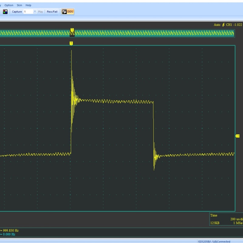
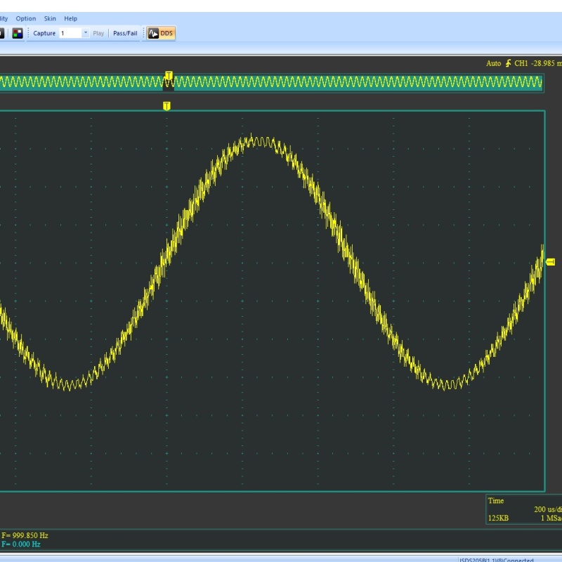
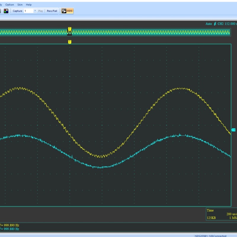
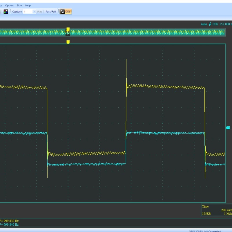
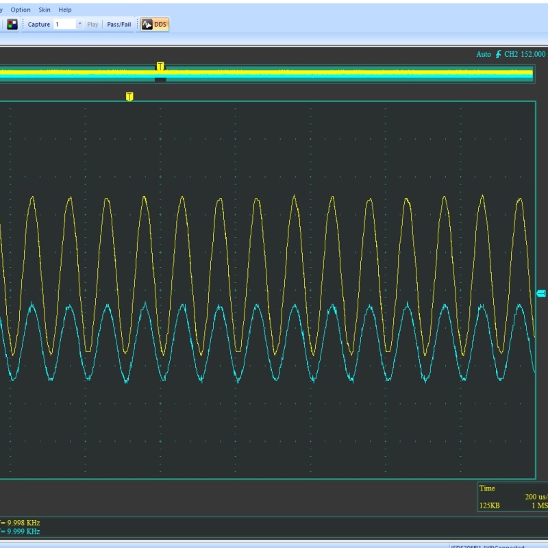
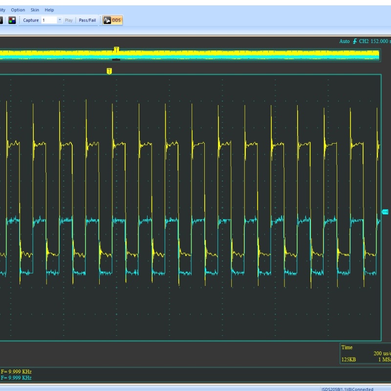
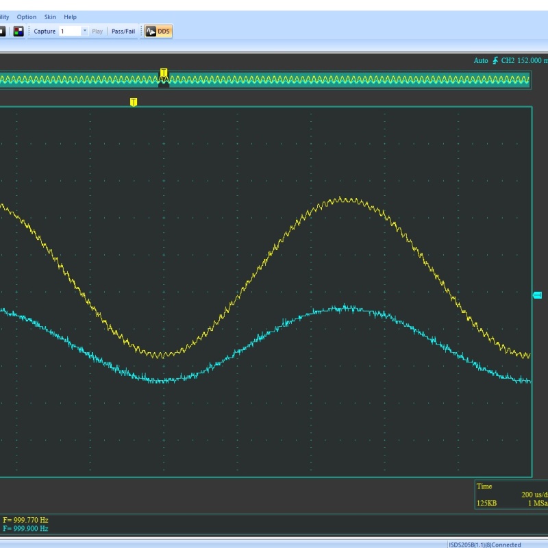
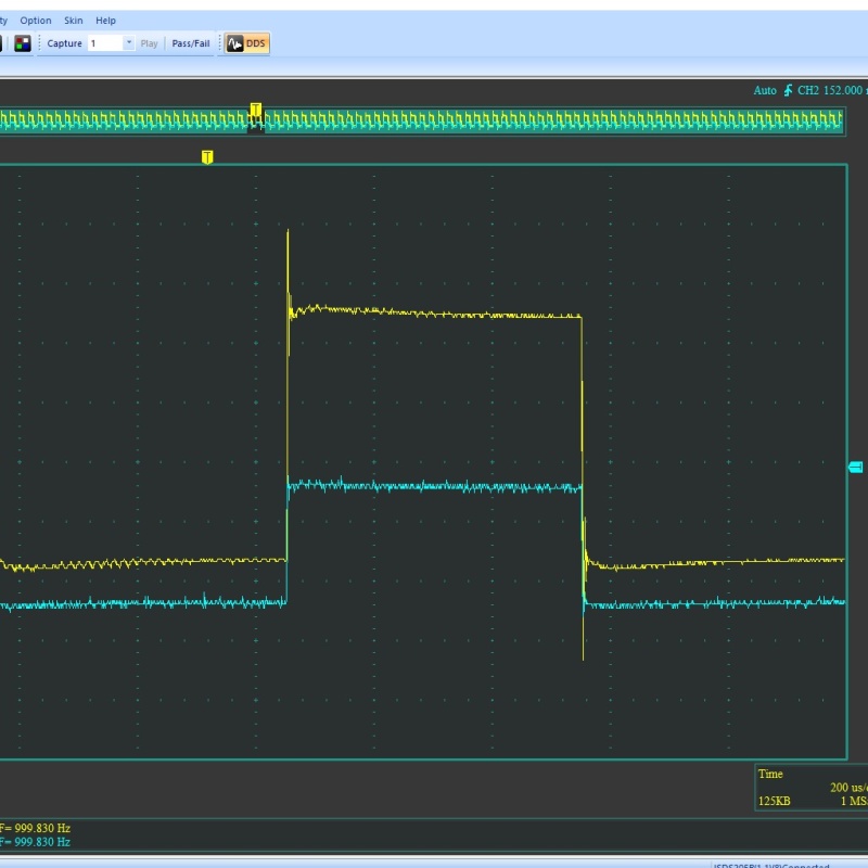
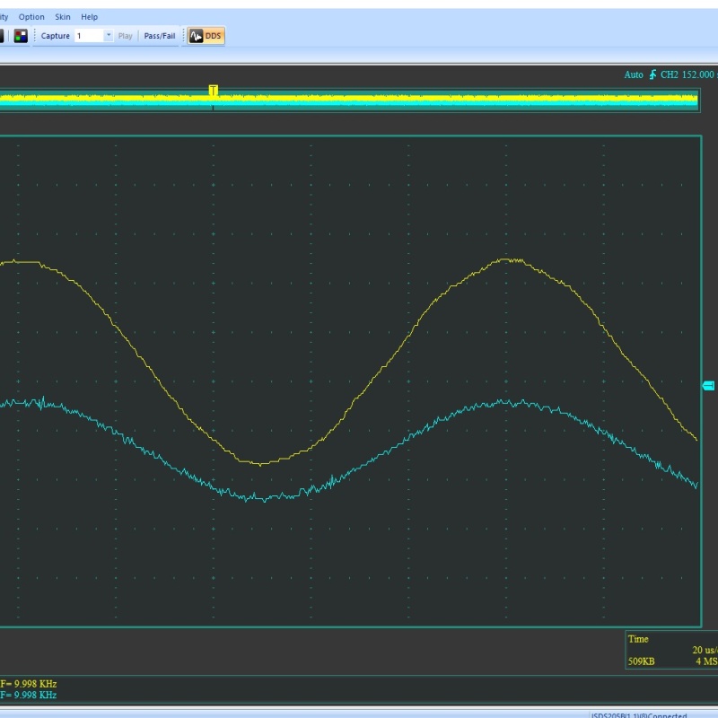
So far so good with testing. I ran some tests with a 100R load with no issues so tonight I moved onto the 4R testing which proved the demise of the first attempt. Both channels looked the same so here is the left channel 1kHz sine wave 1kHz square wave 10kHz sine wave 10kHz square wave.
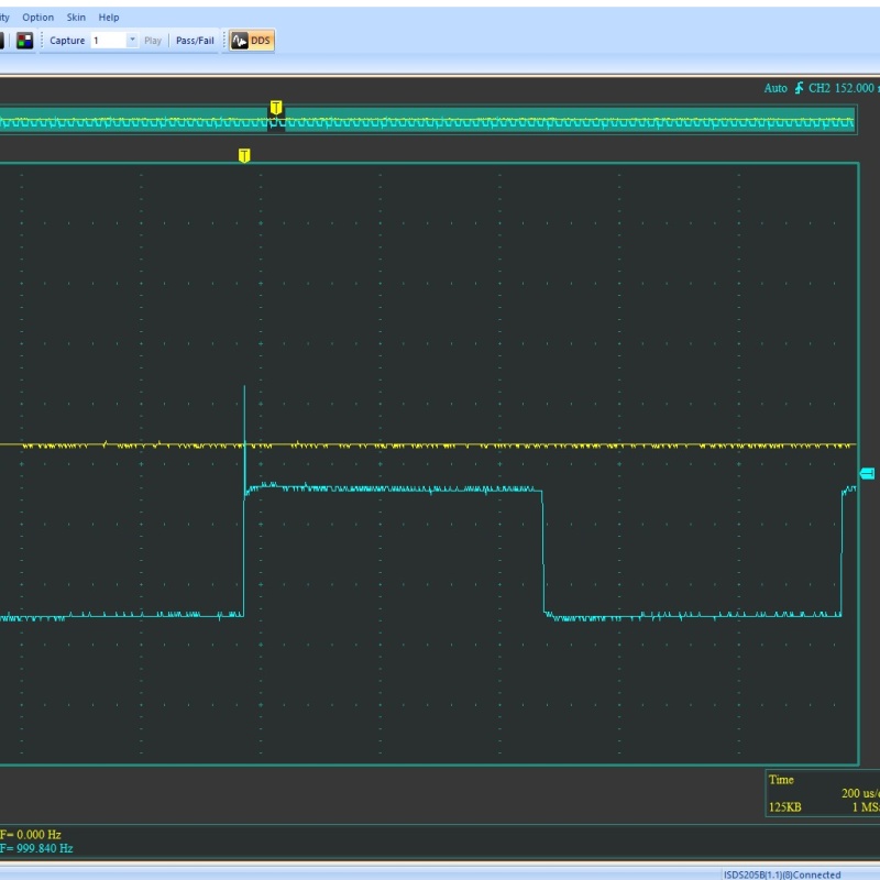
My square wave has a bit of a ring on it which can be seen here with channel 2 connected to the output of the stepped attenuator but not connected to the amp:
This looks to me like an artifact of my test setup: attenuator, alligator test leads etc so I'm not worried about the ringing.
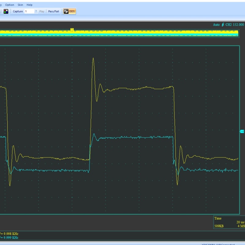
Everything looked good to me: no obvious oscillation so I moved onto capacitive load testing: 4R +3.3nF load 1kHz sine 1kHz square 10kHz sine 10kHz square
A bit of a ring on the square waves but it recovers quickly which looks good to me.
|


