Post by RdM on Aug 21, 2020 23:03:39 GMT 12
I’m in contact with Menno, we were discussing my new digital auto-bias circuit recently.
I'm very grateful for that reply, Colin, because I also soaked up, hmm, odd phrase, read his chapter on auto bias circuits. I'd started drafting a post that actually I'd hoped you might answer, in the "Beginner advice" section. I've read www.tubecad.com/ on these as well, and some forum posts, re say current mirrors.
I'm fixing up this stereo valve Wurlitzer amplifier, a tremendous responsibility, almost finished, new valves are on order, and -
I have discussed with the new owner my proposition to change the cathode circuit from a shared cathode resistor per PP pair, to individual ones and bypass capacitors, I had thought of a say 10 ohm sensing resistor in each and a say 100 ohm wire-wound balancing pot, but then realised to use meters, this will be buried in the bottom of a jukebox and the owner is non technical... it would probably be impractical to get him to check bias periodically. I might not see it much after it's gone. He trusts me but hardly understands this.
With about 80 hrs into it, all resistors and caps replaced, I doubt I can charge even half minimum wage. It turned into a slow labour of love over many months!
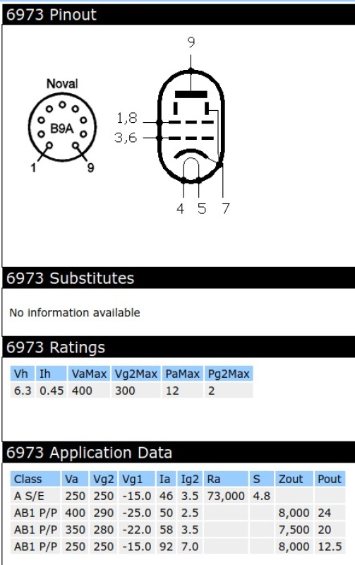
I've already got one matched output pair (6973) and another on the way, so exploring forums as well as tubecad I started wondering if a current mirror setup would work. But I'm not that experienced with semiconductors, not sure how to adapt an example for different voltages, or what new transistors to use vs the old examples in forum posts. I'll find my draft text and put it there in "Beginner advice" in the hope that you might help.
I just want it gone, done, fixed, dealt to. I've had the amp alone for 2 years with a dreamboat first owner who I realised could never pay, then the jukebox carcass was sold to a new owner, who turned out to be very pleasant capable and gave an advance to cover my own initial costs, components, etc. He's also been quite patient. I'm almost finished.
I just want to make it relatively foolproof, beyond just matched tubes with shared cathode resistor, I've already planned for separate ones with sense and adjustment as above. But it would be better if somewhat automatic.
I just want to finish it, it's a nuisance priority after so much time that precludes me getting into any of my own projects or even TM sales while it is unfinished!
So ... maybe tomorrow, that "Beginner advice" section will have a new entry!
Thanks !! ;=})
|
Post by colinf on Aug 22, 2020 3:54:53 GMT 12
Hi RdM, I see. You just want the output stage on the Wurlitzer to be as carefree as possible. Despite appearances, the humble cathode self-bias circuit is also one of the more reliable. It’s super-simple, being made up of just a resistor and capacitor in parallel. I used them on my amps for years. They can be improved upon in a few ways though, one of the reasons to make the auto-bias circuit. But we need to look at what’s going on with normal bias circuits to see why auto-bias is better. In self bias, since the two push-pull valves are run from the same resistor and capacitor, over time the valve drawing the most current will wear itself out more quickly which can lead to premature failure with unmatched valves. Also some unbalanced DC running through the transformer push-pull primary will be working against low distortion and reducing output power. Having the bias independent to each valve works better, and using a separate resistor and cap for each valve is both more reliable and the current can be set a little more evenly between uneven valves. But that configuration also has lower output power as when the class AB1 output stage goes into class B at higher output powers, the capacitors take time to charge to a higher voltage, which reduces the idle current, and that makes crossover distortion. That also occurs on a single bias resistor circuit. So cathode bias is generally best for class A operation with matched valves. My power amps have all been class A. But class A makes the valves run very hot and reduces their life quite quickly. The distortion with matched valves is low though, as the 2nd harmonic cancels out and the valve is biased right in its linear region. Fixed bias is good for output power in class AB and class B circuits. It has the cathodes grounded through a 10 ohm (usually) resistor so you can adjust the set bias on each valve by changing grid voltage. As the valves wear it needs to be adjusted regularly. It’s not a perfect system though either. It’s less reliable than cathode bias as when valves age they build up gas inside them which does a few things. Oxygen poisons the cathode so that it becomes less emissive. Nitrogen and other gases emitted by the valve elements in operation (called out-gassing) contaminate the vacuum and distortion increases, the valve becomes less efficient and it allows the grid to start drawing current. Grid current is the thing that will kill a valve in fixed-bias operation. If the bias is left regularly unadjusted, over time this can get out of control and cause a meltdown, or a fuse to blow. As the valve becomes hotter with high bias the control grid also becomes hotter, allowing it to then draw current. That reduces the voltage on the grid still further, which increases the current through the valve, making it even hotter. Even more out-gassing occurs and damages the vacuum. That’s thermal runaway and makes the anodes glow red before they expire. I always put some form of protection on output valves now, a fuse or circuit breaker on the HT supply to the output transformer, or the cathodes. A circuit breaker might work better in your situation as it’s easily resettable by pressing the reset button. If it keeps popping it’s time to change the valve. Auto-bias is a fixed bias - style circuit that is measured and adjusted constantly so that there’s no unbalanced DC in the output transformer to work against distortion and power. The bias is set accurately whether it’s just been switched on or after a few hours, and with matched or unmatched valves. That increases valve life massively and the best thing is, you don’t have to bias it yourself! Eventually though, the valve will come to the end of its serviceability. On my digital bias circuit I have an LED for each valve that lights if its bias can’t be adjusted, letting you know the valve needs replacing. There is a memory button that when set, puts the bias voltage at a pre-set value that the valve was at when it was last warm, for 45 seconds as the valve heater warms up from cold. Fixed bias needs a negative power supply though. If there's a spare 50v ac winding you can use it. I designed this auto-bias for negative bias supplies only. Perhaps I should design one for cathode self bias as well?
AMR-iFi R&D
|
Post by RdM on Aug 27, 2020 23:06:46 GMT 12
So, I've almost finished restoring this Model 543 amplifier from the Wurlitzer 2600 jukebox. It uses the cheap option of a shared 310 ohm cathode resistor per (stereo) P-P 6973 pair. (with 25uF shared cap, formerly to a section of an HT filter can cap that has now been replaced.) There will now be separate new cathode bypass capacitors. I initially thought I might improve it with a single 620 ohm cathode resistor per output tube, bypassed by 47uF (160V) caps of reasonable size from Jaycar. Made up of 10 ohm for monitoring at the cathode end, then 560 ohm ceramic, ending each pair to a 100 ohm wirewound pot, with its center tap to ground. But because this amp will be in the bottom of a large jukebox, and while I'd thought of a plug in meter (a stereo VU pair from salvage with a switch to compare each pair for balance) with the owner not particularly electronically technical I looked for something more automatic - set and forget.
Matched output pairs have been bought, so that will help. So far I've looked at: "More auto bias circuits" www.tubecad.com/2005/May/blog0046.htm(where he mentions Blumlein’s garter circuit and a current mirror toward the end.) "Blumlein’s garter circuit" www.tubecad.com/2009/04/blog0163.htm(where he also introduces his own cross referenced auto bias circuit) I also came across this chap Flipper (who I remember from rec.audio.tubes newsgroup years ago) using a current mirror, here: (4th post down) (the Princely Pauper amp) www.antiqueradios.com/forums/viewtopic.php?t=226220Some slight explanation in 9th post down. These look simpler than some of Broskies, although similar to his first two. After some research I found his new home page, which shows (among others) a couple of designs with his current mirror. flipper.podserver.info/13FD7%20Mini%20Williamson.htmflipper.podserver.info/StealthAX.htmJust circuits and pictures there, no explanation. (Actually I'm not sure if I have room for a couple of heatsinks even of that size under the chassis, but still.) I'm not entirely clear how I would implement or adapt one of these schemes for the 543 amplifier. I note the extra cathode resistor for one of the valves. Is this because of unequal DCR in OPT PP primary windings? Would I follow the general layout but make the 'built out' total cathode restance the 620 ohms calculated? And how to calculate or guesstimate the two equal resistors values under the transistors? Or, for a passive approach, how would I calculate - or what values should I use - if I were to implement an entirely passive garter circuit, which might take up less room? But then with a classic Blumlein garter I lose voltage, so the current mirror idea seems more suited. I don't know how to adapt either Broskies or Flippers current mirror circuits for the 6973 with 620 ohm cathode resistors. It might not balance as perfectly, but matched tube pairs will be used, and still should be better and safer than a single shared cathode resistor, or two separate going to a 100 ohm pot to set balance initially, which still may drift over time. The current mirror looks to be set and forget, if I can fit the heatsinked transistors in. Maybe I can. But how do I adapt Flippers current mirror to that? The cathode voltage (with shared 310 ohm) is marked at 20V on the schematic, grid at 0V. Would there be more modern easily bought transistors for this than are noted in those quite old posts? All I want to do is make it reliable for quite some years, after putting far too much time into it! ;=})
|
Post by colinf on Aug 28, 2020 7:29:45 GMT 12
Try this:  The 470 ohm resistor should set the current around 33mA per valve if the voltage at the cathodes is 20v. Power dissipation in the right hand transistor should be about half a watt, only a small heatsink would be needed. You can still buy MJE340 and MPSA42 transistors from RS.
AMR-iFi R&D
|
Post by RdM on Aug 28, 2020 20:50:17 GMT 12
Try this:  The 470 ohm resistor should set the current around 33mA per valve if the voltage at the cathodes is 20v. Power dissipation in the right hand transistor should be about half a watt, only a small heatsink would be needed. You can still buy MJE340 and MPSA42 transistors from RS. Thanks so much, Colin! A couple of questions, queries. I neglected to post the 543 amplifier circuit, you may have kindly looked it up, but even in the best resolution pdfs online or the reprinted and bound manual I have here, the HT voltage is a little hard to determine. My guess is that it's either 380 or 360 V. I don't think 300V, compare the 2nd to 3rd numeral. I gather or guess your (beautifully drawn) schematic is from a SPICE model? I've glanced, but haven't yet taken up using it or them. May I ask what version, and where you get models from? Anyway, my question is: How does the actual HT voltage affect the model, resistance values, if say 380V or 360V vs 300V? And there will be a few mA screen current. 33mA is pretty close to the 32.25mA predicted by the 620 ohm 20V, so good. But what about HT volts? If 380V or 360V, would that necessitate changing of values? Looking at the data for 6973, it's quite possible that HT could be 380 or 360 volts I can't measure it yet, because the valves haven't arrived. Plus, there's an evident typo in the schematic for the voltage doubler suggesting that the AC input is 50V If it was a typo for 150V, then maybe 300V HT would be plausible. But the schematic shows clear 0 but a fudged, maybe 6 or 8, for the 2nd characters. Hence I think 380 or 360V. Possibly more likely 380V.
Would either make a difference to the SPICE simulation? Could you give examples of both possibilities, if so? I'm sorry to ask so much! ;=}) But thanks so much, if you can advise on that. So much else going on, it would be a huge help. Kind Regards! Ross Matheson
.
|
Post by colinf on Aug 28, 2020 22:20:06 GMT 12
Hi Ross, looks like the HT is 380v and screen 265v. Wait until you get the new valves and see what the actual voltages are with the 310 ohm resistor. I just wrote the current mirror up on LT Spice in about 10 mins with my voltage calculations around the current mirror. I haven’t performed the simulation with 6973 valves, the 300v HT is just a figure to show where B+ is. (Perhaps I should have just written B+ instead of 300v!) I just took the voltage at the cathodes you mentioned (20v) and worked out the resistor. It’s actually 482 ohms but 470 is the closest practical resistor. I’ll look up the curves for the 6973 later.... The 470 ohm resistor can be changed to set the current through the valve. The current set can be shown from the voltage across one of the 100 ohm emitter resistors. 3.2v is 32mA. The voltage across the two transistor base-emitter junctions is always about 1.2v and detects the current running through the cathode. The right hand transistor mirrors that current for the other valve. Note that this circuit only tracks what happens to the 6973 with the 470 ohm resistor in its cathode. If it has a problem the current through the other valve changes in exact proportion to keep dc out of the primary of the output transformer. Kind regards, Colin.
AMR-iFi R&D
|
Post by RdM on Aug 29, 2020 17:29:51 GMT 12
Hi Colin,
Thanks a lot, that's all very helpful.
Yes I agree it looks like 380V & 265V.
No problem to make up 482 with 470 & 12 ohm.
I found MJE340 at RS Components, Element14, Mouser, but only the last two seem to have MPSA42 as well.
I'll see about ordering on Monday.
I'm thinking now I can probably bolt them to the chassis near the output valves.
Will report back with an update and photo when done.
Cheers!
Ross
|
Post by colinf on Aug 29, 2020 18:44:55 GMT 12
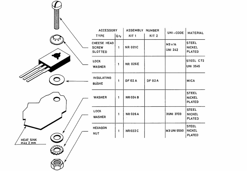
If you’re mounting the MJE340 on the chassis don’t forget to use an insulator! The metal on the back of the MJE is also the collector, connected to pin 2. (Pinout looking at the front with pins down is emitter-collector-base). Insulator 712-8225 at RS, and MJE340 is 714-0997. Use M3 screws. You can use another MJE340 in place of the MPSA42 if you like, it‘ll work the same. Also make sure the chassis itself doesn’t get too hot from heat from the valves.
AMR-iFi R&D
|
Post by RdM on Aug 29, 2020 19:20:18 GMT 12
If you’re mounting the MJE340 on the chassis don’t forget to use an insulator! The metal on the back of the MJE is also the collector, connected to pin 2. (Pinout looking at the front with pins down is emitter-collector-base). Insulator 712-8225 at RS, and MJE340 is 714-0997. Use M3 screws. You can use another MJE340 in place of the MPSA42 if you like, it‘ll work the same. Also make sure the chassis itself doesn’t get too hot from heat from the valves.
Thanks!
Yes, I wondered about that, although in one of his posts linked above "Flipper" mentioned his (was it the same transistor?) case being isolated. However (I once worked in photocopier refurbishment) I've salvaged large junked SMPS boards (great 450V caps etc and heatsinks) and have rubber sheet insulators, clips etc. Still I'll look at those RS insulators.
Probably no room in space on chassis for a 3rd MJE340 so likely to stay with MPSA42. Yes I did wonder how warm the (steel) chassis will get around the output valve bases, but they are in sockets and hopefully although radiating outward there will be convection up. Still I'll see how much space I might have to fit a heatsink underneath.
While the output valves are on the chassis, preamp & driver tubes are on a suspended sub-chassis pcb, so there is room for airflow up around its edges. I'd already drilled holes for and soldered nuts to its flat edge near the output tubes so that I could bolt mount a terminal strip for the various cathode resistor & caps proposed. I'll have to work out how to accommodate the other current mirror components, maybe a small PCB or cheap option veroboard, which I have plenty of.
Pictures later!
|
Post by RdM on Sept 7, 2020 19:07:05 GMT 12
|
Post by RdM on Sept 15, 2020 19:14:37 GMT 12
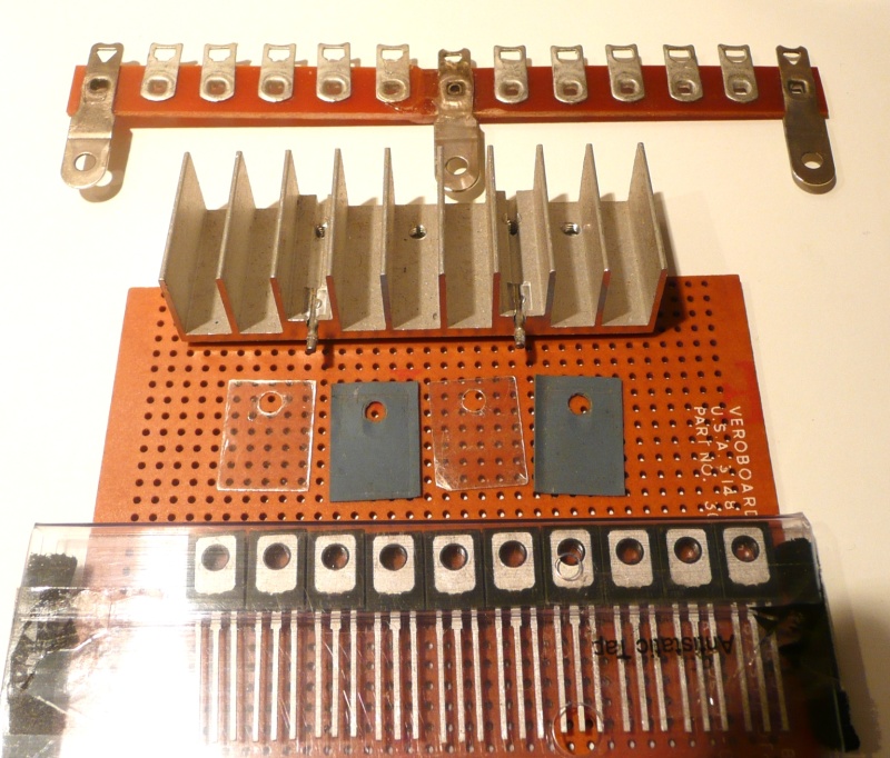
If you’re mounting the MJE340 on the chassis don’t forget to use an insulator! The metal on the back of the MJE is also the collector, connected to pin 2. (Pinout looking at the front with pins down is emitter-collector-base). Insulator 712-8225 at RS, and MJE340 is 714-0997. Use M3 screws. You can use another MJE340 in place of the MPSA42 if you like, it‘ll work the same. Also make sure the chassis itself doesn’t get too hot from heat from the valves. Thanks Colin;- I decided since steel is such a poor thermal conductor anyway I'd look through my junk boxes for saved heatsinks. Those insulators at RS are for TO-220; it's seems hard to find TO-126 specific ones, but with the same 3mm hole I suppose they would be OK. I don't have any insulating shoulder washers that fit. I'm wondering about using nylon M3 screws and nuts.
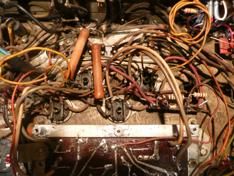
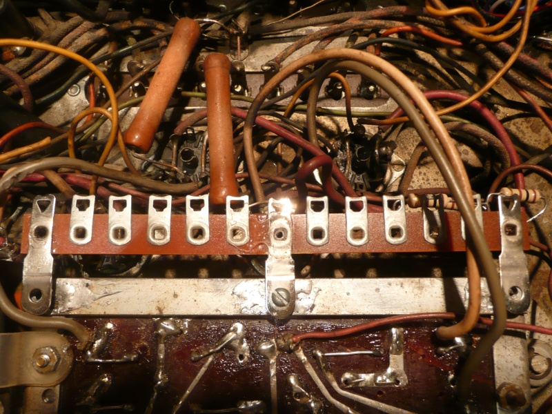
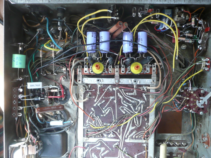
Poking a metal M3 bolt through looks to contact internal metal in the MJE340? Doesn't seem safe. I found a couple of small heatsinks pre-threaded for M3, one has four holes but unevenly spaced. I'm thinking I'll buy this set of drill-thread-countersink all in one step units from TradeMe: Here's the space I've got to work with. I'd already drilled holes in the sprung pcb sub frame near the output valves and soldered nuts down, to receive a custom tag strip made by joining two together with epoxy and a brace underneath, to take the earlier components thought of for separate cathode resistors, sampling resistor, 100 ohm wirewound pot for each channel. The curled up yellow wires are the previous shared cathode connections that ran way back to sections of two separate can caps. I have to bring out four individual ones to the tag board, clipping the shared connecting wires.
(There are lots of tag strips in this chassis, so it looks the part.)
You can see the original two shared cathode resistors. The LH one was open circuit. I've since unsoldered and reoriented the yellow & grey (looks brown) wires on the right to come in from the side and not be in the way. (Phase splitter outputs to power tube grids.) The 100 ohm carbon films visible are replacing 47 ohm carbon comp screen resistors. Since the PSU doubler caps have had 100uF replaced with 270uF I thought they might be safer, after reading this: (can't find the reference!) (You can just see half the underside of one bottom left top pic, not yet connected. I'm going to replace the ancient round green SD1 diodes too.)
Anyway, I thought maybe a small strip of veroboard. I might only need two vertical holes visible, perhaps mounted on standoffs with the tag strip bolts might be enough. With the heatsink mounted approx over the sub-chassis edge. Not sure if enough heat-sinking if free-floating attached to veroboard. But maybe. I also found I have two mica TO-220 insulators and a few silicone ones. I read though that one shouldn't re-use those.
Maybe with a new craft knife blade I can split the mica ones into 4? ;-) Progress slow at the moment, some major family distractions, and also while I want to make it look neat, I don't want to spend too much more. But every so often I'm having a little think about it. I have yet to test the transistors for hfe, lay out on paper and match pairs just for the sake of it. Just a catch-up! PS: Here's an old diagram of TO-126 mounting! I can get nylon M3 from Jaycar, an easy bus or walk.
The recycled heatsink tapped for M3 had a captive spring lock washer at the head of the bolts. Cheers!
|
Post by colinf on Sept 16, 2020 18:53:27 GMT 12
Hi Ross, Thanks for the pics. With TO126 transistors you can use a TO220 insulator. The hole in the insulator is 3mm, M3 size. No need to use an insulating washer on the screw, and you can still use a metal screw as the hole in a TO126 is insulated, unlike the metal tab of a TO220. Make sure the hole in the insulator covers the metal back next to the screw hole. Best not to split the mica from a single mica washer into 4, that would make it very brittle indeed. Use thermal paste with a mica washer. If using a silicone washer it’s best to use a new one each time, as an old one has been compressed in the pattern of the old transistor previously and may not develop consistent thermal contact with a different transistor. No need to use thermal paste with a silicone washer. Also not really necessary to match the hfe of the transistors as the two 100 ohm emitter resistors take up any difference between base-emitter voltages of the two transistors. But knowing the gain might be good so you can calculate the base current at 30mA emitter current on each transistor, and thus calculate the resistor on the collector of the MPSA42 (R6 and R3 in my lash up circuit) more accurately. Looks like the circuit board could do with a good clean, and it looks like one of the pads is almost touching the metal mounting bar. Is it a ground pad? Is the circuit working ok with replaced 310 ohm cathode resistors? Do that before adding the new current mirror circuit. Good luck! Regards, Colin.
AMR-iFi R&D
|
Post by RdM on Sept 16, 2020 23:30:40 GMT 12
Today I bussed & walked in the sunshine to Jaycar and bought a 4x mica set for TO-220 with shoulder insulate washers, and all the resistors, obsessively matching them to ~ 1%, as has been my wont. Absurdly they had nowt below 22R in carbon film, so alternate for 12R 1W to be sought to make 482. They had 12R in 5W, overkill, 80c ea. I bought two anyway. Matched 470R 5W in shop. I'm still sorting through ideas for mounting all this yet. I'll look for a smaller 12R. Ideally all the mirror components mounted in a small space. They actually also had quantity adhesive thermo pads for TO-126 and washer sets but more than I wanted to pay, I took 4 mica. Aware I only need grease for mica but that's a great careful summary, thank you! This has been a useful read. sound-au.com/heatsinks.htmThanks. I'll see if my little tester does gain(?) Yes it's filthy with ancient flux, last of the concerns before/after at the end of rehabilitation. Later pictures should clarify! I don't see which one of the pads is almost touching the metal mounting bar. Possibly camera angle. I don't think so, but where, NSEW? Thanks for looking! Ah! I see, no;- ta - that spatter looking original is on a pad out from ground all around under the bar. Quick reply, and thanks;- I wonder about a couple of other things. [Forgotten, saved for later] The circuit (amplifier) is not able to be tested yet, the replacement valves are in transit. I could try with original circuit (replace dud shared cathode R) then with individual cathode ones, before current mirror, yes certainly. Still with a sampling resistor to measure with I guess. Matched output valve pairs, one here, one to come, and others to come before it can be tested. 7199, 12AU7 pairs. Thanks! I really appreciate the communication! PS: One wonder was: how accurate are the other resistor values (near enough, I guess and accept!) - and which way up or down in value does which main one (like R5 470/482) influence current? I've got R4 68R close, does this make much difference? An odd thought about OPT DCR differences between primary PP sections. Turns ratio is the same, some transformers are optimised for for class a or ab perhaps, but how much does differing DCR between primary sections matter? Thanks for your thoughts and contacts, comments.
|
Post by colinf on Sept 17, 2020 19:22:57 GMT 12
Increasing R5 reduces cathode current. Using 470 ohms in place of 482 ohms increases the current only a little, around 1mA. No need to stress over the absolute value. Same with R4, the 68 ohm. The value isn’t critical and indeed you could short it out or increase it to 100 ohms and it would make no difference to the current. The current mirror circuit will automatically compensate for it. It’s there so you can measure the voltage across it to work out the current running through the right hand valve, around 2 volts with a 68 ohm resistor= 30mA. It should directly mimic the current through R2 and R1, 3v with 30mA current. It’s also there to limit heat dissipation in Q1 and limit current in the event of a short circuit. I usually like to get things clean and working properly before adding the new circuitry, but that’s just me! Some output transformers are wound from the centre core outwards. So the + phase to the centre B+ tap may not have exactly the same resistance as the - phase to B+ tap. The number of turns is the same, but it takes a longer length of copper to get the same number of turns on windings further out from the core, so the resistance increases. The disadvantage of a straight forward winding technique is increased and dissimilar leakage inductance and leakage capacitance which affects the frequency response. That’s a good reason to wind high quality transformers with a number of similar sections, all connected to the + and - phase alternately. Some transformers are wound with bifilar techniques, where the + and - phases are wound together in the same section, with the two wires side by side.
AMR-iFi R&D
|
Post by RdM on Sept 17, 2020 21:34:02 GMT 12
Thanks for the great and succinct answers, Colin.
I'm working on it, will update.
|
Post by RdM on Oct 21, 2020 22:35:06 GMT 12
First time playing with VeroCad & TinyCad, since I have some veroboard pieces and don't think it worth doing a PCB for this one-off. (I don't have PCB skills anyway as yet!) The netlist from TinyCad didn't really work since so many components were not 'connected', but it got me the components in to VeroCad. So while not being able to autoroute etc. at least I was able to place components manually. And then place links manually & etc. This was a first learning exercise;- when I came to save it I found that the default was 32 strips, whereas my board had 34, so I had to re-adjust then drag down each lower section component to suit. A brief check, I hope I've got it right, but I'll have to triple check to be sure! ;=}) It's a bit asymmetrical, constrained by the placements of the MJE340s on the heat sink, and maybe I could do better, but as a start. 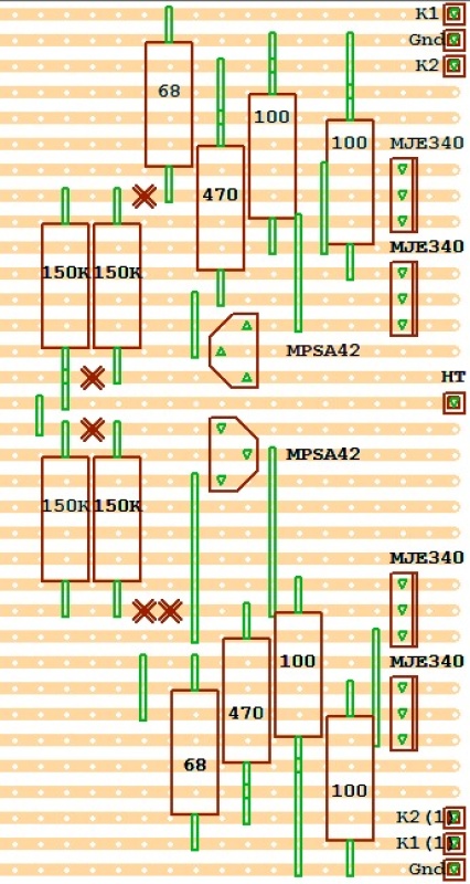 It's been an interesting exercise. The heat sink will be on the RH edge, and have air flow out to above. The bypass caps will be mounted off that board, on a tag strip already planned for with a passive adjustment idea, before I discovered the current mirror idea, and I might take Colin's advice to try the restoration out on first run - I'm converting it from a shared cathode resistor per P-P channel to individual bypassed ones - with that set-up, individual cathode resistors ending in a 100 ohm wire-wound pot, center to ground, with a series each 10 or 100 ohm resistor to check current balance. It seems sensible advice, make sure the amp is working before introducing the current mirror SS circuitry. I'd even thought of a rotary switch to select cathode sampling resistor pairs, and maybe converting an on hand stereo VU meter to read balance... But really, there's no room for that, and the owner would probably find it too complicated or forget to check as valves age. Hence my enthusiasm for the current mirror idea, even if the technology not fully understood does seem a bit 'magic' to me! While veroboard might seem a bit ugly to some, understandably, vs pcb etching, I happen to have some of the former, there is a community for it, and while I understand the principles and have read up on techniques, and a friend has often made his own pcb's, I have no experience in that so far. So since this will be hidden underneath the chassis of a valve amplifier in the bottom of a Wurlitzer jukebox, improve reliability, I think OK. I'll post more photos as I get the build/restoration completed, likely in a separate thread for the complete amplifier restoration. Thanks!
|
Post by RdM on Dec 30, 2020 21:13:19 GMT 12
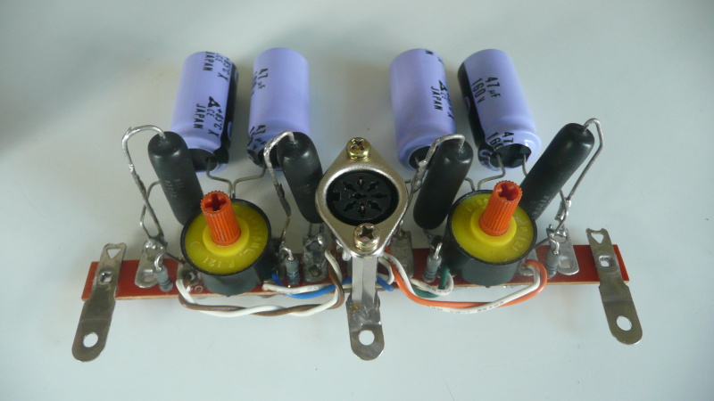
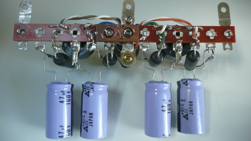
I'm converting it from a shared cathode resistor per P-P channel to individual bypassed ones - with that set-up, individual cathode resistors ending in a 100 ohm wire-wound pot, center to ground, with a series each 10 or 100 ohm resistor to check current balance. It seems sensible advice, make sure the amp is working before introducing the current mirror SS circuitry. I'd even thought of a rotary switch to select cathode sampling resistor pairs, and maybe converting an on hand stereo VU meter to read balance... So going on from that idea, I made a small adjustable DC supply, and found that the old stereo VU meter joined pair would read ~ 30mA in a lower third of the scale. Tested it across 10 ohms. 15 ohms might give a larger reading on the scale. But too late now, I've built a temporary tag-strip set up for adjustable cathode bias.
To make the desired individual 620 ohm I have (oversized, just to hand) 560 ohm then 10 ohm exact metal film sense resistors, going to a wire wound 100 ohm pot center to ground.
Now I just have to organise a socket/plug connection to switch out to the dual meter for checking balance. I've checked that I can balance the resistor chain, it's pretty good. +- 1 ohm.
The ironic thing is that is all just a temporary set up, to check the basic restored amplifier workings, before I build the automatic bias current mirror circuit and install that instead.
But I think it's a good idea to just test it passively first, one thing at a time.
Having matched pairs of output tubes to come, why not make separate cathode resistors adjustable too?
So mocking that up, still not having clipped out the original shared cathode resistors - which by the way are wired to chassis, chassis has grounds all over the place, and I am thinking of taking those output cathode grounds directly to the bottom of the real power supply cap - terminal, hence those black wires, not just lamely nearby to the steel chassis, as they are now.
Just a mock-up, via a center bolt, annoyingly nudged out of alignment before photo!
But again, absurdly intended just as temporary to check operation.
I have about a week to construct the current mirror replacement if otherwise it all seems to be working OK.
I certainly hope it will be!
So much delicately to think about on somebody else's old '60s jukebox valve amplifier. Most commercial jukebox restorations just replace caps, not even resistors. I've gone to the extreme and replaced all resistors as well, even matching 5% down to 1%.
Oh Vey
|
Post by colinf on Jan 2, 2021 22:04:48 GMT 12
The cathode resistors ideally connect to the power supply ground of the stage driving it. Good luck!
AMR-iFi R&D
|
Post by RdM on Jan 3, 2021 0:42:26 GMT 12
The cathode resistors ideally connect to the power supply ground of the stage driving it. Good luck!
Thanks!
I'd actually just logged in intending to delete my earlier post. Thinking I need to start again, reformulate it. May yet still do so.
Off topic (manual vs auto bias), ugly pictures, and besides I've accidentally snapped the joined tag strips, so am starting again to make that temp outboard section stronger. Plus have now bought standoffs for an 8 pin DIN socket and plug to (switched) check each channel pair with an old stereo VU meter, have yet to mount the socket. And then (maybe I find and separate old ribbon cable) connect 8 wires from each of the 10 ohm sense resistors, switched to each side of a stereo VU meter to compare.
Again, a temporary lash-up to check basic amp operation before making and trying out the auto bias current mirror board. One thing at a time. There's little room to spare. One of the two original shared cathode resistors was OC anyway, and the old cathode caps were in sections of dead now replaced multi section can caps, so ... May as well make individual caps with some balancing adjustment facility to start with, I thought.
But my understanding was that the PP pair output stage cathode resistors should connect as directly as possible to the earth/gnd/-ve end of the HT supply to their anodes.
My one chance to do that. All the other stages grounds are fed through various wires and ground plane connections multiply to/ all around the steel chassis. Incl. the driver stage.
I mean, not only do various ground connections get made to various welded tags on the chassis, there are also wires connecting them as well. Weird, miniature hum loops? Or not trusting connectivity of the welded tags to that chassis? Thin tinned wires.
So I thought since 1st HT +ve feeds the OP pair anodes, then goes off through RC filters to feed screens then drivers and preamp stages, each with circuitous returns to ground & through the chassis, that I would be helping the output PP pair by taking its cathode resistor ground returns directly to the -ve of the (voltage doubler) HT cap, which itself connects to chassis some inches away for all the rest, rather than have them (as now) just connected to a steel chassis return many inches away, randomly and conveniently for original construction, but ... ?
Also, that instead of the OPT secondary being grounded to chassis as it sits, to separate that from chassis and just send a feedback ground back to where it comes in on the pcb. No need for OPT secondary currents to be circulating in the steel chassis?
Anyway, just thoughts, still working it out ...
Still learning about best practices! I hope! ;=})
And hoping to make this restoration an improvement, which it already is in component quality, but maybe in layout as well, those pesky grounding issues...
|
Post by colinf on Jan 3, 2021 21:50:05 GMT 12
Ah, a grounding of convenience on this chassis then. The concept is good, use a low impedance ground plane to connect all circuit grounds to. It’s not quite as simple as it seems though. Magnetic eddy currents from the power transformer circulate through the chassis and a result in potential differences at each ground point. RF interference today is very high with mobile phones, wifi, bluetooth etc and the UHF RF potential at different points across an unshielded ground plane can be high, low impedance as it is forming high Q resonances. Ideally the chassis should be grounded at one point only, generally near the input socket, and all circuit earths wired to it (star grounding), or in series as the circuit goes from input to output. The output earth should not be far from the input earth so that any RF on the interconnect shield and speaker earth goes straight to the chassis, the closer to the single point connection the better. The chassis then acts as a large shield for the circuit inside. Mains earth goes there as well. If there’s a potential for a ground loop from connected equipment the star ground can be lifted with a ground lift circuit, but the main chassis containing the power transformer is earthed directly to mains earth.
AMR-iFi R&D
|
Post by colinf on Jan 3, 2021 21:50:38 GMT 12
(I should copy this to the grounding thread!)
AMR-iFi R&D
|
Post by RdM on Jan 27, 2021 21:24:17 GMT 12
I'm converting it from a shared cathode resistor per P-P channel to individual bypassed ones - with that set-up, individual cathode resistors ending in a 100 ohm wire-wound pot, center to ground, with a series each 10 or 100 ohm resistor to check current balance. It seems sensible advice, make sure the amp is working before introducing the current mirror SS circuitry. I'd even thought of a rotary switch to select cathode sampling resistor pairs, and maybe converting an on hand stereo VU meter to read balance... So going on from that idea, I made a small adjustable DC supply, and found that the old stereo VU meter joined pair would read ~ 30mA in a lower third of the scale. Tested it across 10 ohms. 15 ohms might give a larger reading on the scale. But too late now, I've built a temporary tag-strip set up for adjustable cathode bias. To make the desired individual 620 ohm I have (oversized, just to hand) 560 ohm then 10 ohm exact metal film sense resistors, going to a wire wound 100 ohm pot center to ground. Now I just have to organise a socket/plug connection to switch out to the dual meter for checking balance. I've checked that I can balance the resistor chain, it's pretty good. +- 1 ohm.
The ironic thing is that is all just a temporary set up, to check the basic restored amplifier workings, before I build the automatic bias current mirror circuit and install that instead. But I think it's a good idea to just test it passively first, one thing at a time.
So I did organise an 8-pin DIN plug-socket arrangement to sample across the 10 ohm resistors.
The previous attempts had broken, so I strengthened the tag-strip join with a longer strip of copper clad board and epoxy flood.
I will put an insulating strip underneath this, since it's only a few mm away from the valve sockets.
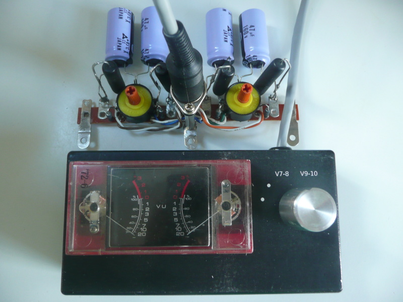
So next to put the dual meter and switch in a box, I reluctantly bought a $5.20 one from Jaycar, and carved out holes in it ...
I had to learn a bit of Inkscape to create the label, self adhesive A4 glossy laser print label cut out for the black box.
The underside;- I used some network cable so I could keep track of the colours...
The top side, a box that should let me check balance, just a rough lash up so I can check before going to automatic.
The valves which will enable actual testing might arrive this coming weekend.
It'll be a relief when it all works OK! ;=})
Let's hope that it all works out nicely!
~ RdM
|
Post by Owen Y on Jan 28, 2021 8:36:36 GMT 12
(I should copy this to the grounding thread!) Yes please do that colinf) or we can copy it over if you wish.
|


