Post by colinf on Jul 30, 2020 1:02:08 GMT 12
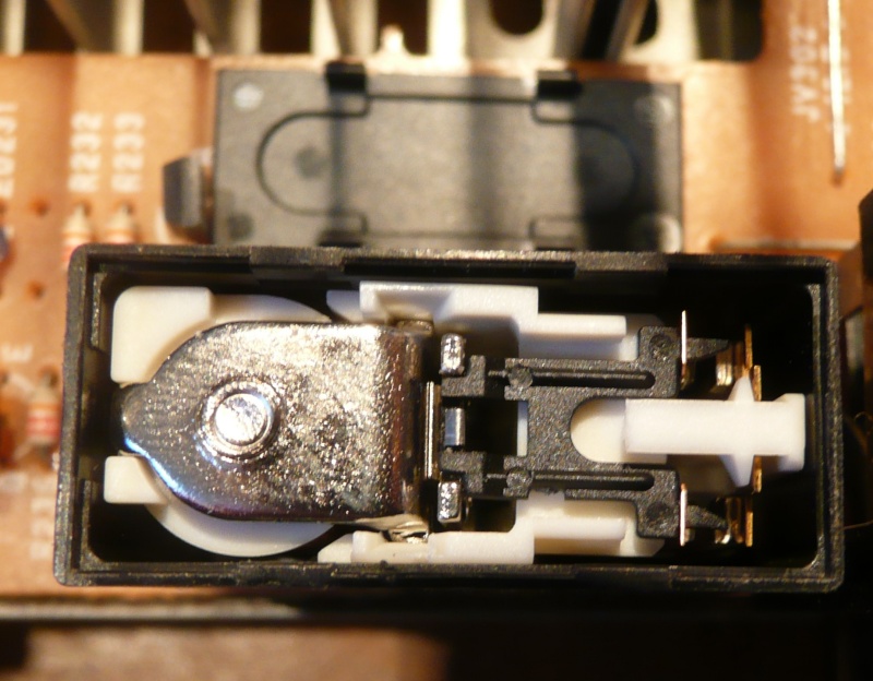
I brought out my Denon POA-4400A poweramps to clean them and have a listen. I thought they sounded quite good, the monoblock configuration having that characteristic openness and the inviting 4400A warmth. But upon switching them on after they’d not been on for a while the sound in the left amp crackled into life after a second or two of music. Ah, I thought...speaker relays. They need a clean! Most solid state amps have a relay in-between the poweramp circuit and speaker terminals intended for speaker protection and ‘de-thump‘ when you switch the amp on or off. But over time the relay switch contacts can become oxidised or dirty which leads to high, inconsistent resistance and added distortion. Considering a speaker is 8 ohms or so (or 4 ohms for some) any resistance in series with the signal is going to do a few things. The damping factor will increase, the relay contacts dissipate power which makes them hot which might damage them, and since the resistance is undefined the distortion increases massively. You can get anywhere from 0.001% increase in THD with a clean relay to 100% (no sound) with a severely oxidised one, and anything in-between. Knowing the Denons were functional but with imperfect contacts I’d guess the added distortion to be below 0.5%. The circuit is capable of very low distortion, around 0.002% or below for normal volume. It was definitely time to clean the relays in the Denons! So I pulled them apart on the bench, unsoldered them and gave the contacts a good going over, all without thinking to take any photos to put on here...so I undid the cover again and took a photo of the relays.  After removing the relays and unclipping their plastic covers, they have two parallel contacts inside. I decided to do a before- and after-clean resistance measurement. The meter said one set was measuring 7 ohms!! The other around 1 ohm. They should be less than 0.05 ohm. The 7 ohm contact was so deeply oxidised I didn’t clean it once but had to do it 4 times to get it to read low resistance! The left channel had the highest resistance, the right channel was around 0.5 ohm for one contact and 1 ohm for the other. So I was excited to have a listen. TBC
AMR-iFi R&D
|
Post by jon on Jul 30, 2020 11:12:39 GMT 12
That provokes a thought... I wonder how many people get trapped into an upgrade cycle or dumping something for lack of a simple fix!
I'd like to say not me, however... much pondering.
|
Post by colinf on Jul 30, 2020 18:22:24 GMT 12
Yes, I guess things like this kind of servicing and maintenance creep up on you over time...a bit like realising the clothes you wore when you were younger don’t fit anymore! But that’s another story.... Thorsten at AMR considered relay distortion to be so pervasive he eliminated them in the AM-77, replacing them with a speaker protection system that switches off the power supply and shorts the speaker terminals together.
AMR-iFi R&D
|
Post by colinf on Jul 30, 2020 18:35:32 GMT 12
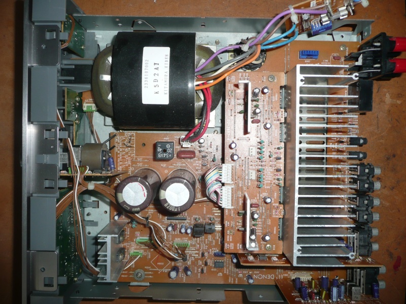
...I was interested to have a good listen after the relay clean in the Denons. Well I was expecting it to be a little better but honestly, the increase in transparency was not subtle! The left channel sounded louder, the image snapped into focus solidly and the feeling that it sounded ‘right’ pervaded. Dynamics also increased and it was a joy to listen to a properly functioning 4400A. I was so inspired I thought I’d take a look at the big old girl, the Sansui BA-F1. Her speaker relays haven’t been cleaned as far as I know, and that amp dates back to about 1981. I took some photos on the bench this time.  
AMR-iFi R&D
|
Post by Owen Y on Jul 30, 2020 19:59:31 GMT 12
That variac looks a bit like mine.. 
|
Post by colinf on Jul 30, 2020 22:18:37 GMT 12
Nice, we used to use ones similar at work. My voltac has been with me since about 1990 and has been around the block a few times. It’s become just about the most useful item of test equipment on the bench after the multimeter! So I keep it right on top of the bench so I can use it easily. 
AMR-iFi R&D
|
Post by cartridgeguyonline on Jul 31, 2020 8:55:09 GMT 12
Q please. are the relays on the sui under those clear plastic covers ? What do you clean the relays with ? contact cleaner and cotton buds. Can we have a pic of what the relays look like.
|
Post by Owen Y on Jul 31, 2020 10:54:58 GMT 12
My voltac has been with me since about 1990 and has been around the block a few times. It’s become just about the most useful item of test equipment on the bench after the multimeter! So I keep it right on top of the bench so I can use it easily. In what situations typically would you recommend using a variac? With valve amps, you can check heater supply & HT volts before installing valves, but I guess it is v much more useful with SS? Or even for reforming low voltage caps?
|
Post by colinf on Aug 1, 2020 0:55:19 GMT 12
The relays on the Sansui are next to the power supply capacitors, one each channel. You can see it has 4 separate relay contacts, all connected in parallel on the circuit board. I guess Sansui knew about relay distortion and aimed to minimise it by using 4 sections in parallel instead of the usual one. The relays look very accessible but to clean them you need to get the brittle plastic cover off, and on the BA-F1 it’s slightly harder than it looks. I wanted to unsolder them and pull them apart on the bench to minimise damage but looking at the way the boards are mounted, the wiring for the output stage is underneath with very short wiring to this board. To get a soldering iron in there with desoldering wick would mean undoing the heatsink with output transistors all nicely wired to it! There had to be a better way. I unscrewed the boards and rotated them in such a way that I could lever two small flat headed screwdrivers under the side clips. It worked!  Now with the contacts exposed I could go about operating the relay manually by gently pushing the solenoid down and measuring the switch resistance. To my surprise it had very low resistance, less than 0.05 ohms, the limit of my meter. Amazing considering their age and lack of maintenance. I usually clean them with contact cleaner and seal them from further oxidation with switch contact lubricant. The Sansui’s relays were in almost perfect condition so didn’t need much of a clean. To reassemble them I pushed down the cover but left it slightly above the clips so that it would be much easier to get them off next time. The Denon’s relays needed a proper restoration. The oxide layer was severe and so hard I ended up scraping it off with a blunt screwdriver, and did it 4 times. It’s best not to use sandpaper for relay contacts as the random scratching can cut deep grooves in the contact area. A blunt screwdriver works better, but only if you need to resort to it! Severely damaged relays really should be replaced. I sealed the contacts afterwards with switch lubricant. Back to the Sansui....we’re not out of the woods yet, the BA-F1 has speaker switches for A and B speakers. The speaker signal runs through these switches, which are mounted underneath, meaning a trip to the bottom of the amp. It’s great these old amps are quite serviceable with the bottom panel easily removable, something that’s very rare these days! The bottom hasn’t been off for a while and the dust buildup wasn’t too bad.    The speaker switches looked a bit oxidised and measuring them revealed slight resistance of 0.1 ohm. Cleaning them with contact cleaner restored them to low resistance.
AMR-iFi R&D
|
Post by colinf on Aug 1, 2020 1:14:43 GMT 12
While the bottom was off I checked the fuse and discovered to my horror, it was set incorrectly!   The note clearly says for 120v use an 8A fuse and for 240v use a 4A one. The fuse was still the 8A one...this amp must have been imported from North America. So I changed it for the 4A fuse recommended for 240v. The last thing I want is a meltdown of the transformer if something happens!  One happy, healthy Sansui BA-F1!
AMR-iFi R&D
|
Post by colinf on Aug 1, 2020 1:52:50 GMT 12
“In what situations typically would you recommend using a variac?“ All life situations except brushing your teeth. And not for critical listening as they don’t sound as good as a proper step down transformer if you need one, eg. from 260v to 240v like some parts of Western Australia. For valve amps you can set the DC heater voltage at a certain mains voltage, ensure correct bias at standard mains voltage, fault finding at low voltage before the fuse blows etc. For SS it’s almost mandatory to use one to test an amp that you don’t know what has happened to it. Also for new builds that you want to make sure the electronic parameters you just calculated are in fact true. Oscilloscope used for most other stuff. A few weeks ago I had a SS integrated amp on the bench that the customer mentioned had experienced a power surge. It looked normal inside and the rectifiers were fine, as were the output transistors, ie. no short across the power supply rails. After replacing the fuses I turned it on at low voltage on the Voltac, watching intently for the telltale signs of excess current and unexpected heat. At about 60v all the horses broke loose and the Voltac hummed loudly, expressing its displeasure at a shorted amp. I spun the dial to off in an instant. Checking the amp, it turned out to be a partially shorted power transformer.
AMR-iFi R&D
|
Post by colinf on Aug 2, 2020 18:21:57 GMT 12
So on to the sound of the Sansui after the relay clean. After the huge improvement to the Denons’ relay clean I wasn’t really expecting the Sansui to be much better than before as the relays were in ok condition. And indeed, putting it on showed it to be its normal self. From cold it sounded grey, thin and uninteresting but remembering this amp takes a long time to warm up I left it on for a bit. I’m not sure what happened between about 1 1/2 to 2 hours but it just became incredibly transparent and open, dynamics were great, excitement was back! I can see why the old BA-F1 is such a revered amp. So if you have a classic SS amp or two make sure the relays are serviced, it can make a fundamental improvement to the way it sounds. The Denons came alive.
AMR-iFi R&D
|
Post by Owen Y on Aug 2, 2020 21:34:09 GMT 12
Thanks colinf - that's encouraging. Although depending on the amp, it might be a surgical-like procedure to get at these relays.
|
Post by RdM on Aug 29, 2020 18:42:54 GMT 12
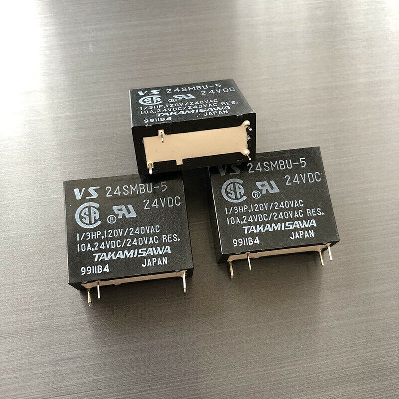
... depending on the amp, it might be a surgical-like procedure to get at these relays. Unfortunately that looks to be the case for the little Denon amp here. The relay is right next to the speaker terminals and up against the back panel. I took that off hoping to see how to lift the cover off, not obvious. So I noted the brand and number, and amazingly found photos of the exact a similar model at ebay. (footprint is quite different!)
Looks like the case slides off from the bottom. I've since spotted 4 clips for the top and prised it off. So I can just see the contacts, on the right, but not as accessible as they'd be if the case was off and I could get at them from the sides. In fact there are little plastic guards obscuring them (see bottom right) and they don't look very easy to get at effectively enough to really inspect, clean, measure, from the top.
Which means I'm going to have to take the whole main board out to unsolder it to do that, if I can't clean them from the top, which seems unlikely. No removable bottom panel, so everything has to come out, be unplugged, the output board with heat-sink before the main board. Jolly japes! ;=})
I remember reading elsewhere that to clean relay contacts, one should soak a small strip of (counter intuitively) glossy, not matte paper in contact cleaner or maybe isopropanol, close the contacts on it, and with slight pressure on them pull it back and forth.
I suppose that's for contacts that aren't too badly oxidised or pitted... comments?
|
Post by colinf on Aug 29, 2020 19:05:06 GMT 12
If you can push the relay contacts together from the top, you can measure them by putting one meter probe on the output of the poweramp (you’ll have to locate that!) and the other from the relevant + speaker terminal. It looks possible to get a fine flat screwdriver into the contacts. I’d be worried with cleaner soaked paper at getting a glob of ripped, wet paper down in there that will be impossible to remove! If it’s really oxidised, the relay is so close to the back you might be able to loosen the board to lift it up slightly without unwiring it, and use solder wick to unsolder it. It’s not a plated through-hole board so that should be relatively straight forward. While you’re under there look at the RCA input sockets’ soldering as some might have cracked with use. Resolder as necessary. Also the speaker terminal soldering.
AMR-iFi R&D
|
Post by Owen Y on Aug 29, 2020 19:42:58 GMT 12
I rather like those R-core TXs, having used one only once. I didn't think you could get them big enough for a power amp.
|
Post by RdM on Aug 31, 2020 19:06:36 GMT 12
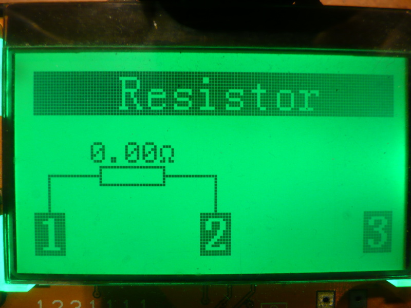
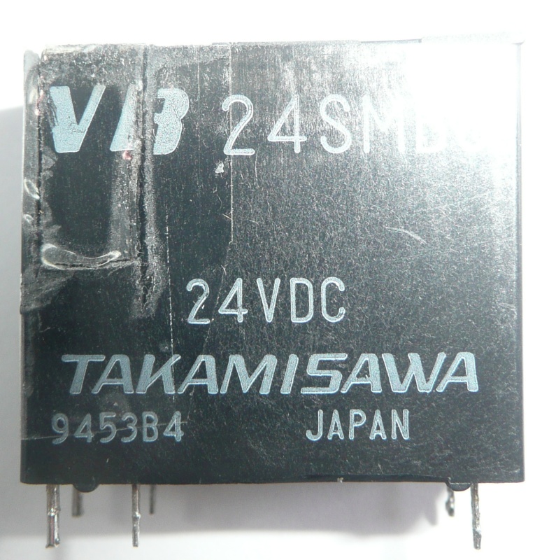
In the end I decided it was easy enough to take the board out. 4 screws for the heatsink, two plugs to the power board. Two daughter cards, HT connector, a little plug top left by the TX, and I was able to turn it over. 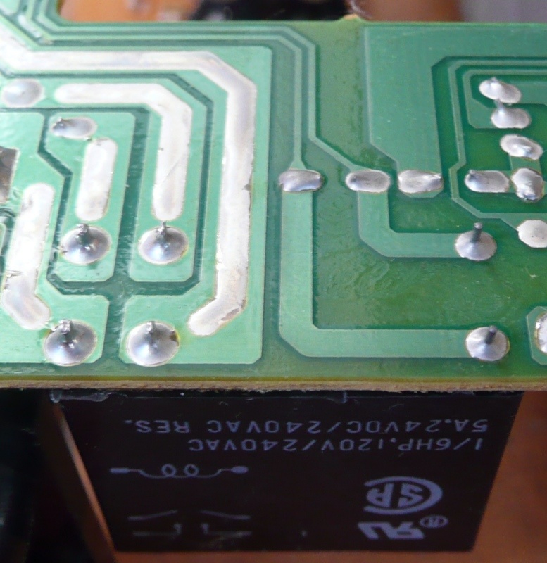 It came out easily enough, solder sucker worked better than braid. But when it was out, I realised I was mistaken about the cover coming off. It looked sealed, and that black edge is so thin it looks contiguous with the white; in fact I could hardly feel it with a fingernail, and couldn't slide a craft knife blade under it or even do much trying to cut along the join. 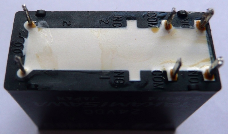 Perhaps it was moulded like that, but it wasn't coming off. Still, worth getting out so I could measure it, and easier to attempt a clean from the top with it in hand. I've got one of those LCR-T4 Mega328 transistor & component testers, which will go down to .01 ohm, calibrated so that it does read 0.00 ohm with the leads shorted (I'm not sure exactly which version I have but it's been very handy. Although mine came without a case.) (A page about it here: reefwingrobotics.blogspot.com/2017/10/lcr-t4-mega328-component-tester.html ) Before cleaning I got 0.11 ohms and 0.66 ohms. To clean it I whittled down a wooden cotton bud stick (I always by the wood ones vs plastic) to thin and flat enough to just get in between the contacts past the little plastic tags, soaked it in isopropyl alcohol, and was able to burnish both contacts with it, several times. After which I got 0.01 ohms and 0.05 ohms. 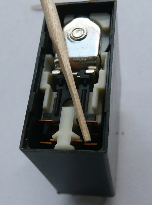 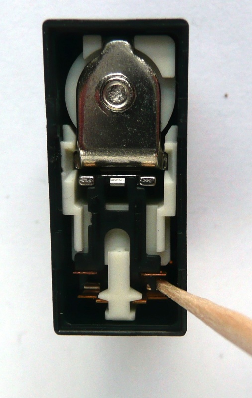 While I had the board out I touched up a few aged looking solder joints, then reassembled, checked the bias was in spec, tried it out. Balance more equal, and although I've only cycled it a few times yet, it's started up reliably on L & R every time so far. So I'm calling it a success for the moment.
|
Post by colinf on Aug 31, 2020 20:10:37 GMT 12
Not too hard to pull out the board by the sound of it. That’s good the resistance lowered quite a bit. Clear photos!
AMR-iFi R&D
|
Post by RdM on Aug 31, 2020 21:12:53 GMT 12
Not too hard to pull out the board by the sound of it. That’s good the resistance lowered quite a bit. Clear photos! Thanks! The camera is 13 yrs old and fairly modest now but still quite sufficient for TM & forum pics; a Panasonic DMC-TZ3.
A mix of "Intelligent ISO" and Macro modes, cropped from full res, and even then downsized (unlike some earlier ones) to 800 pix w or h, so actually some loss of resolution. (I set the thumbnails at 800 resized vs the default 100.) Holding it steady is important; the above hand held but hands braced to hold steady; for TM I usually use a tripod. Then select the best of several, etc. But yours are fine! ;-)
In retrospect possibly I should have scrubbed more at the higher resistance pair. That cotton bud wood is ~ 2mm diameter, whittled by hand; perhaps I could have made it more even, looking at the macro pic now.
Plus, I only had isopropanol on hand, no fancy Caigs Deoxit or anything else.
The biasing instructions; there is no adjustable pot, rather, as I've seen in other amps too, just an instruction to cut a resistor if it is too low. In this case the range is wide, 2mV to 40mV across test points! After the advised 10 min wait I had 8.2mV & 6.0mV. After 20 mins, 8.0mV & 5.5mV. I know this is slightly off-topic, but am I right to think that a higher bias current (within that range) will give "higher fidelity"? I mean, higher idle current so further away from the AB or B crossover point, but is this toward class A at lower listening levels? Sure I realise that the output pairs will run hotter. But any sonic advantage?
I'd have to look at the schematic again to see if a pot could be put in place, or what resistors to trim to fine tune it.
I noted that the driver IC pair on the power board with small ali heatsinks ran fairly warm, too hot to touch after a few secs, maybe 60° plus, then two unheatsinked transistors on the main board run hotter still... I looked around for some flat small square U copper ones I'd salvaged, but couldn't find them. Maybe it's no worry. Perhaps silicon can run hot, and it has survived since the early '90's! But the main power heatsink felt quite cool, although of course all this was with no signal and no load, as per manual.
The last thing I haven't done yet is to input from a signal generator and measure/compare output from each channel with balance control at center detente. Anyway, thanks for the original post, because it inspired me to get in and do this! ;-)
|
Post by colinf on Aug 31, 2020 23:37:45 GMT 12
Scrub until clean! Well, as much as you can anyway. If the resistance fails to come down very low, it might be better to replace the relay. Since 0.05 ohms is still higher than 0.01 ohms I’d keep scrubbing to see if it comes down even further. At 2A output (the peak of 20w average power into 8 ohms) 0.05 ohms x 2A = 100mV. And power dissipation in the contacts would be 0.1v x 2A = 0.2w. Not much but could add audible effects. High current relay contact resistance is unstable and varies with current, unlike a real resistor. So you’ll want to keep the contacts as clean as possible. Here’s a graph from Bob Cordell’s book Designing Audio Power Amplifiers. It shows how you get transconductance (gm) doubling and thus added distortion from setting the bias in a class B amp too high. Of course if the current is very high with large heatsinking, say 1A bias current, the gm doubling will stop at higher volume so you don’t notice it. Low volume levels are what the ear picks up on most, where the power required to reproduce the harmonics of instruments is the dominant sonic factor. So a bit of bias increase might make it sound better. A lot of bias increase, as in class A operation puts the transistors in their fastest and most linear current gain so sounds best. The price of class A is hot, large heatsinks and inefficiency. My rule of thumb for SS is if you can touch the heatsink or transistor comfortably you should be ok. Hotter, and it should really have a heatsink. The junction temperature is what needs to be kept within limits. 
AMR-iFi R&D
|
Post by RdM on Sept 1, 2020 0:02:40 GMT 12
Scrub until clean! Well, as much as you can anyway. If the resistance fails to come down very low, it might be better to replace the relay. Since 0.05 ohms is still higher than 0.01 ohms I’d keep scrubbing to see if it comes down even further. At 2A output (the peak of 20w average power into 8 ohms) 0.05 ohms x 2A = 100mV. And power dissipation in the contacts would be 0.1v x 2A = 0.2w. Not much but could add audible effects. High current relay contact resistance is unstable and varies with current, unlike a real resistor. So you’ll want to keep the contacts as clean as possible.
Hmm. (tempted toward "Bugger!":-))
I might have to take it apart again, except that next time I might only have to take the cover off, and attempt further cleaning from the top, without desoldering it. OTOH, it was easier to measure at the pins when it was out. Still, maybe I can grab the edges of those copper strips. It was odd that at a couple of attempted measurements the tester claimed it was a diode ...
Thanks for the other part;- I'll look back through the service manual to see how those emitter resistors are placed, what the to be cut one is, if etc.
But what is the vertical scale in that chart? 0.9 to 1.0 what? Distortion? Thanks!
|
Post by colinf on Sept 1, 2020 3:31:25 GMT 12
Gain of an emitter follower output stage. ie, the input voltage to the emitter followers multiplied by (0.9 to 1.0) = output.
AMR-iFi R&D
|
Post by RdM on Jun 4, 2023 0:45:35 GMT 12
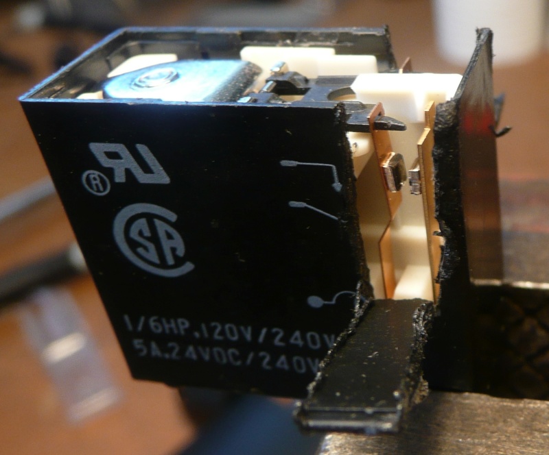
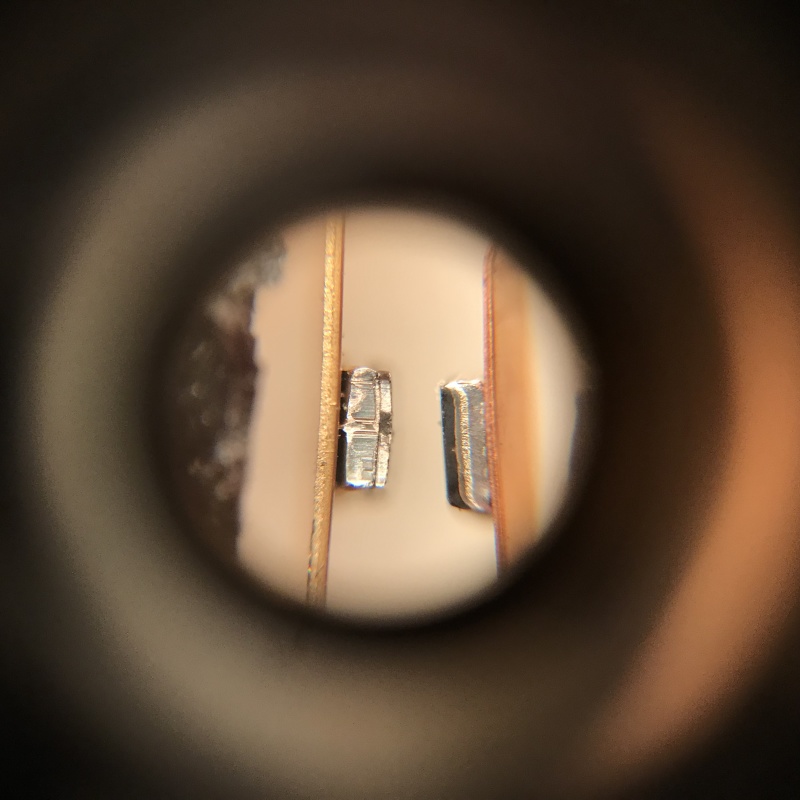
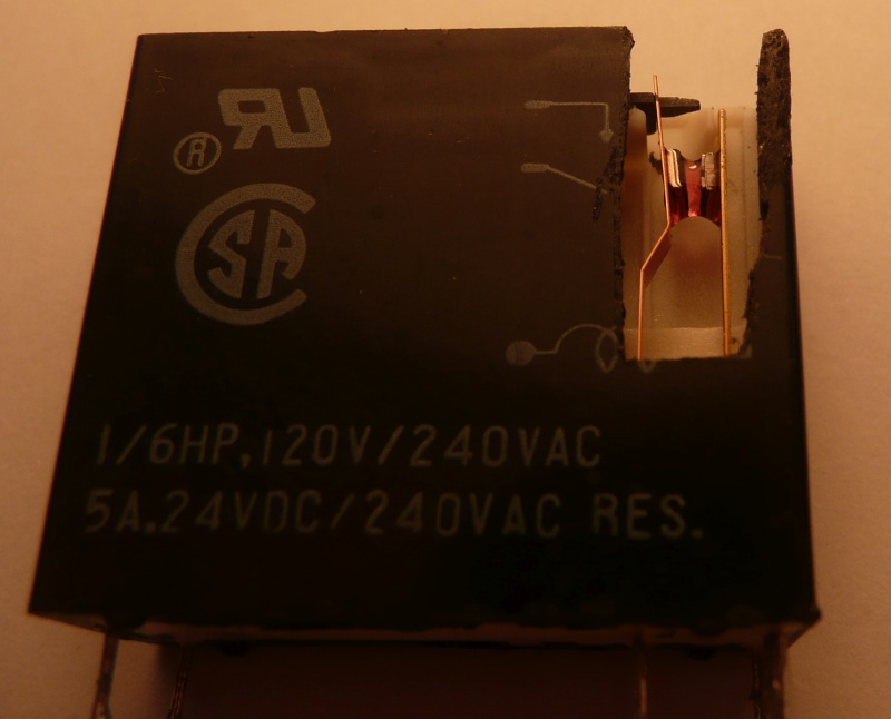
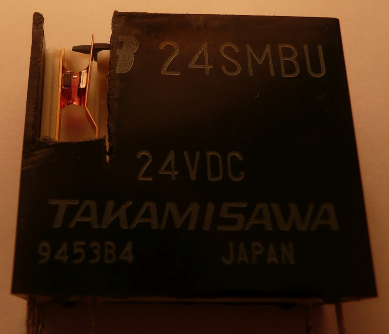
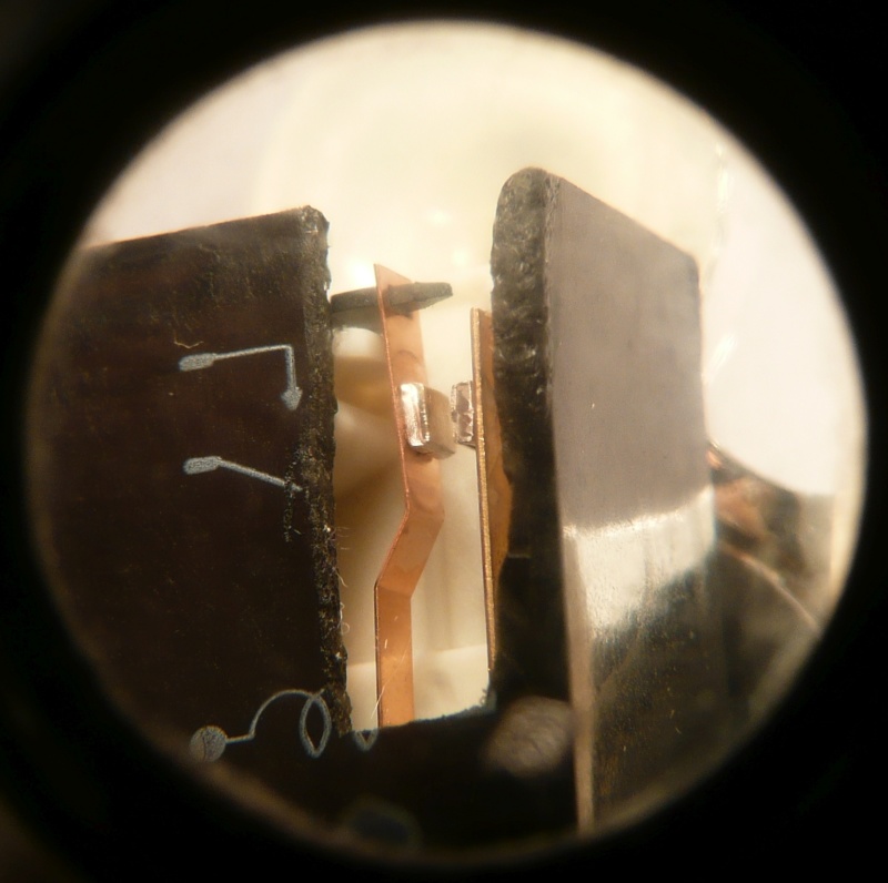
Well, and I'm surprised to see how long ago it was, that didn't work out. Feelings of sensing distortion, then one channel dropped out completely again. I decided that more radical surgery was needed, since I'd hardly been able to clean or see the contacts from the top. So in a vice, a heated craft blade, vertical slits, bent back. Don't worry, I cleaned up the edges before reinstating them with tape to support.
The contacts were totally black! (This from a small digital camera through a scratched not great plastic 'jewelers loupe' lens, nevertheless it worked!)
I'd bought some quite expensive Caig Deoxit earlier from Jaycar, so thought this might be worth trying it out on. I applied it overnight, viscous enough to stick between contacts.
Actually there was still some black after that. I found some fibrous paper cleaning tape from my days in the film library. Almost there ...
But I still wasn't satisfied. In the end, I used a bit of Brasso dropped on a small strip of cleaning tape, between the contacts held together, polished, flushed with isopropanol. And they turned out very nicely cleaned. No photo. But finally resistance on each relay contact went down to zero limit, both sides.
And now, after a brief disconcerting first try when it didn't work, then realising I'd plugged in the pre-in-out links incorrectly, it's working wonderfully!
The slight distortion feeling and imbalance between channels has gone.
I'm enjoying it right now.
Oh, I did tape the relay case cut parts up again, with nice no residue expensive 16mm film splicing tape ...
And later taped a piece across the top, hoping to seal it atmospherically ...
Anyway it just sounds so much better and solid now ... wow, that relay cleaning has really worked! ;=})
Thanks!
|
Post by sadface on Jun 4, 2023 8:40:03 GMT 12
Nice work.
Your hands must be much steadier than mine!
|


