Post by sadface on Dec 8, 2021 19:17:45 GMT 12
Another school of thought considers steel or other magnetic material undesirable. Eg, DNM with their perspex chassis and casework. Tricky one isn't it.
I've noticed if one looks at the lower cost and more mainstream gear: home theatre amps for example, they tend to be stamped sheet steel.
If one looks at some of the more expensive stereo equipment there is lots of aluminium.
Is ali used in more expensive gear because it is the superior shield or is it because ali is more easily worked into interesting shapes?
The more I think about it, the more confused I get.
|
Post by sadface on Dec 8, 2021 19:49:47 GMT 12
OK, I'll be the 'Devils advocate' What is the big deal with dual mono amplifiers ? Why the emphasis on channel separation to eliminate crosstalk ? My understanding is that in the real world( live performance in normal room ) the typical crosstalk is around 30 - 35 % The left ear is always going to hear some of what is aimed at the right, and vise versa. Not arguing, just asking out of interest.!! Everybody knows that dual mono is better because its just better alright....
I understand the basic theory and it makes sense to me in principle. Little beyond that, I'm just a hobbyist were just enough brains to be dangerous and little more.
I've also seen it said that separate transformers is unnecessary, merely separate transformer windings to get the same effect.
I will say that the best amps I have heard have been monoblocks, I view dual mono as a slightly cheaper version of mono blocks as one is at least saving money on the chassis.
Dual mono certainly won't hurt if it is within the budget of a build, but of course for the extra money spent on the doubling up of the power supply, perhaps that money could have been better spent elsewhere.
In my case, I got the pair of transformers rather cheap several years back. A single trafo of appropriate size was about the same money. The caps, rectifiers, small heatsinks etc were all purchased on clearance so total cost wasn't too bad.
There seem to be plenty of high end amps that don't use dual mono construction. Perhaps it is merely fashion or a marketing gimmick.
As a builder, I build the best way I know how and dual mono construction fits in the mold. Probably a better builder could get better results without....
The next run of power amps I build will start with a standard single trafo approach as proof of concept. Then I will build a set of monoblocks in the same design. It could be a good opportunity to see if there is a noticeable difference.
By way of comparison for now: I said I would reserve judgement however after 2 evenings worth of listening. I will say that this gainclone sounds nicer than my Rotel RB1060.
The most obvious difference is the ability to pick out individual voices.
A favourite test track of mine is Perry Como Goodbye Sue
Obviously not played off youtube....
With the gainclone it is much easier to pick out the individual voices in the choir.
Of course this could be more a function of the gainclone itself rather than the dual mono construction, or perhaps a bit of both.
|
Pundit

Post by peter0c on Dec 9, 2021 13:20:49 GMT 12
An embarrassing question perhaps Graham, considering the 'cross-talk' that naturally occurs in a live recording venue let alone your room and not forgetting the less-frequently-seen nowadays centre speakers. Maybe the issue is less of cross talk but what happens the the current available for say the left channel when the right channel is pumping out bass notes. Transient inter-modulation distortion is I think the correct term but I stand to being corrected. I think that it can only be measured in dynamic conditions and not the normal sine wave / square wave tests of say John Atkinson from Stereophile. Again I stand to be corrected. In my listening experiences (and those of the late Murray Dick of Ecofan) the best power supply configuration is a single power transformer with (of course) one primary but two secondaries, each independently rectified and smoothed. Still, sometimes it is better to have two moderate weight monoblocks than one massive stereo amp.
|
Post by RdM on Dec 9, 2021 17:34:23 GMT 12
Apropos of nothing, except dual mono supplies in the same integrated chassis, I have a Pioneer A-77X stashed on a high shelf here. www.hifiengine.com/manual_library/pioneer/a-77x.shtmlTrue dual mono for the power amps;- I forget, but maybe the 3rd transformer was for the preamp sections. The faults came about with the proprietary source selection switches, which also switched LEDs, replacements unobtainable. It seemed very grunty and controlled before the source selection switches became a problem. Quite impressive. In investigating, one day I'd forgotten to reconnect the feedback wires - that was interesting, too! Louder, more "alive"? But anyway, I'm saving it to be either a power amp or to try the expensive Caig deoxit stuff squirted into the almost sealed switches.
|
Post by sadface on Dec 10, 2021 7:17:03 GMT 12
Back to drills presses....
Does anybody know where I might get a new belt for a standard 1/4HP drill press?
My old ryobi gives off a lovely burning rubber smell during operation.
|
Member

Post by dc4 on Dec 10, 2021 7:30:38 GMT 12
Hi Sadface,
Try Hector Jones Ltd (www.hectorjones.co.nz). Ph (06)878 9049.
They had an on/off switch for my old Ryobi planer that had failed.
Regards,
Derek.
|
Post by colinf on Dec 12, 2021 23:01:50 GMT 12
IME stereo systems, where the grounding is shared between channels, can sound excellent and have very good soundstaging. The Kondo Ongaku is a good example. It has a stereo power supply and stereo grounding. Digital systems almost always share the grounding between channels and have typical separation better than -100dB. Dual mono and monoblocks to me means the separation of the grounding between channels, not just the power supply. Monoblocks take it a step further where the chassis are separate between channels. From a technical point of view, limited channel separation from an electronic device while playing acoustic recordings shouldn’t have much effect on the perception of soundstaging, except when it becomes around 20dB or less. Yet hearing dual mono and monoblocks in action, that would suggest this isn’t the case. It’s widely known cables influence the sound, and not just from an inductance, capacitance, resonance, skin effect and impedance matching point of view. The material quality makes an audible difference eg. silver vs copper, cotton vs ptfe etc. So when referencing this info to dual mono construction, it’s sonically beneficial to have separate channel grounding to avoid sonic artefacts that influence the soundstaging, and even harmonic structure. Monoblocks are the next step up in sonics. Similar to separating the grounding materials between channels, the chassis material and construction also influences the sonics, but this is a more subtle effect and the improvements are mostly noticeable on very revealing systems. The Kondo Gakuon are monoblocks for a reason.
AMR-iFi R&D
|
Post by sadface on Dec 13, 2021 20:42:08 GMT 12
I'm a little uncertain as to what you mean by separating the grounds between channels.
Are you referring to the situation like I have with this build. Where the only ground common ground connection between the 2 channels is at the chassis earth?
Or do you mean something more like a class II device where there would be no common earth connection?
|
Post by sadface on Dec 13, 2021 21:03:52 GMT 12
Also a wee progress update.
After a week in my main system, I'm satisfied everything works properly and sounds fantastic.
Last night I took everything apart, packed the parts into a few boxes and took the chassis back into my sheetmetal guy.
I will have the height chopped down to 90mm from the previous 125mm. Since I'm no longer constrained by the old lid, I'm making it shorter since the tallest part is the heatsinks at 75mm.
90mm seemed like a good compromise between making the amp shorter but leaving plenty of space to breath.
He will also fold up a lid. Apparently it should be ready later in the week. Then the real work starts!
With the shorter height I will have to redo some of my mains wiring scheme.
I also need to drill extra holes to secure the lid and hold some p clips for the mains wiring and ground wiring.
I will do a final clean of the pcbs then spray them with some Jaycar pcb lacquer.
I will also have another look at a few wiring details and consider if I might do certain things a bit better.
|
Post by colinf on Dec 14, 2021 20:59:00 GMT 12
The power supplies and grounding are separate between the channels in your build, so that’s dual mono. Monoblocks are still usually earthed together at the mains, and in your build the common earth is at the chassis. So that’s still dual mono, but in a common chassis.
AMR-iFi R&D
|
Post by sadface on Dec 17, 2021 18:37:23 GMT 12
Thanks for the clarification. That was always my understanding also.
|
Post by sadface on Dec 17, 2021 18:43:04 GMT 12
G'day Guys,
Some progress today!
I got the chassis back from the sheet metal man.
Height chopped down to 90mm.
Lid made.
It think it looks pretty cool. I like the industrial look.
Not cheap, but perhaps not expensive either. The base was $100 or so if I recall correctly. The lid was $150, so $250 all up for a custom chassis in 1.2mm steel. From looking around on aliexpress etc, I don't think I could get a superior chassis for cheaper by the time one factors in shipping. Probably inferior in terms of my requirements; steel, dimensions etc.
   
If I am lucky I might find some time over the weekend to start drilling some mount holes and thinking about the hole pattern and size I want for venting out of the lid.
|
Post by sadface on Dec 19, 2021 21:53:20 GMT 12
I got a bit of time this afternoon while Her Royal Highness was napping. A bit of progress made.
Much scribing, a lot of auto centre punch and a bit of vivid afterwards to get an idea of what the pattern will look like.
I'm pretty happy with how it will look, I'm not yet certain on what hole size. I'll start with 4mm and see if I want it bigger afterwards. I intend to go over the hole centres with the auto centre punch again with the punch set on a higher strength (not sure what the term would be there). The idea being to make the centres a bit deeper and hopefully harder to wander from once I start drilling.
Before I start drilling, I've got some more holes to measure out for mounting the lid to the base.
I will also need to remove some material from the back where the flanges on the lid foul with the I/O connections.
I am also toying with the idea of dispensing with the wooden front and using some 5mm or so steel plate instead.
The hard bit would be removing material for a power switch, it might simplify some other aesthetic considerations.
|
Post by sadface on Jan 8, 2022 22:17:35 GMT 12
G'day Guys,
A good bit of progress over the Christmas holidays.
I've drilled fresh holes at the back of the chassis base to mount the lid to. I decided to go with M4 rivet nuts. I considered just using some recycled sheet metal screws but I like rivet nuts and it seems a bit more robust.
I've drilled the holes in the back of the lid for mounting into said rivet nuts. One amusing flaw I discovered was that when I specified a 20mm flange on the lid, it was going to foul on my I/O jacks so I will have to remove a little bit of material from the flange to clear the I/O jacks. This will probably come last after all of the rest of the drilling etc is done.
I had to readjust the holes for mounting the front panel to account for the new chassis dimensions and work around the 20mm flange at the front of the lid too.
I've done the hardest part which was drilling out the 408 (I think) vent holes in the lid with a step drill. Since, the chassis is too deep to get to the centre with my drill press I had to do it with my trusty cordless drill. So far it has been done to 4mm, however there was one hole where I was pushing a bit hard it it is 75% of the way to a 6mm hole. Thus the final hole size will be 6mm. I'm pretty stoked with the hole pattern so far.
Finally, I've cut out the front panel in 30mm brown wood ply. This one needs a small hole chiseled out for the power switch.
All in all, a good amount of progress amongst all the hectic business of a young family.
In theory tomorrow, I will have time to take the lid vent holes out to 6mm but we'll see how the day goes.....
|
Post by Citroen on Jan 9, 2022 18:21:40 GMT 12
Excellent job. I admire your DIY skills.
Maybe don't bother redrilling all the holes, just choose a few to make a pattern, your initials, a wave, a smiley face, whatever...
|
Post by sadface on Jan 9, 2022 22:00:50 GMT 12
G'day Guys,
Some good progress today.
I found time to drill out all the vent holes to 6mm. 408 holes without an accident.
I'm very happy with the result.

I've got a bit of work to do deburring all the holes.
I also have a bit of work to sand off all of my measuring lines etc. Get everything smooth and purdy looking ready for paint.
|
Post by colinf on Jan 9, 2022 23:10:25 GMT 12
Looking good. Do you have some vent holes under the heatsinks on the bottom panel? That would allow better cooling of the heatsinks as the heat rises, and cool air is being drawn in under the heatsink.
AMR-iFi R&D
|
Post by sadface on Jan 10, 2022 20:33:49 GMT 12
G'day,
Yep, I've got some vent holes under the heatsinks.
|
Post by sadface on Jan 31, 2022 14:05:31 GMT 12
Hey guys,
Progress is slowed again recently.
I've de-burred all of the drill holes but that's about as far as things got.
Maybe next weekend I will get some time to continue.
At this stage I need to remove a bit of material on the rear flange of the lid to clear the I/O jacks.
Then it is sanding the lid ready for priming and painting.
|
Post by sadface on Feb 9, 2022 21:04:48 GMT 12
G'day Guys,
I had time for a bit of progress over the long weekend.
The lid is now at the painting stage.
I cut out a bit of material from the flange at the rear of the lid to clear the I/O jacks.
Sadly, my ozito dremel died halfway through the job and so I had to switch to the angle grinder. I'm not nearly as good with the angle grinder and so the cut wasn't quite as precise as I would have liked.
Luckily this is at the rear of the amp where it won't be seen but I'm still a bit bummed as I was going for perfect on this build.... such is life!
I finished deburring all of the vent holes and gave everything a good wizz with a power sander with 120 grit and 240 grit paper.
  Notice the small rounded bit in the removed material on the right hand side in this photo 
Currently the lid is down in the basement receiving some coats of etch primer before I paint it.
More photos to follow in the coming days.
Progress is stalled on the base part of the chassis while waiting on some letter/number punches.
|
Post by sadface on Mar 2, 2022 15:06:19 GMT 12
G'day Guys,
Progress has been glacial recently. All the current work is all noisy power tool stuff and time when i can make lots of noise is severely limited by the sleeping baby. I have to negotiate an hour here or there with my wife around all of the usual weekend chores and keeping baby out of too much trouble.....
Metal work is almost entirely done.
The 2 halves of the chassis are finally done with cutting, drlling, rivet nutting.
Sanding the base was the last noisy job but its all done.
A few coats of primer and things are looking great.
    
This was my first foray into spray painting so I learned a bit as the coats progressed.
This was all from the same can despite the different shades. I've got few runs to lightly sand back before putting on the top[ coat.
Ironically, both my wife and I find the colour of the etch primer really pleasing... especially the thicker coat on the base.
A future build might just get primer with a clear coat on top.
|
Post by colinf on Mar 2, 2022 19:50:23 GMT 12
Looking good. I like the gloss grey on old Radford valve amps.
AMR-iFi R&D
|
Post by sadface on Mar 6, 2022 21:07:55 GMT 12
G'day Guys,
Painting is done.
Results were mixed. I've not done much spray painting before so this was once again a large experiment.
Hammered finish Rustoleum is really cool stuff. It did take a bit of getting used to as you will see from the photos.
The inside of the base. I did this part first so this was my first and worst experiment.
You can see on these 2 photos, that I really achieve the 'hammered' part of the finish very well apart from around the edges.
Inside of the lid, I did this second. A better finish here but not consistent and there was a big puddle in one corner....
Bottom of the base. Not so good here, you can see my spray strokes....
  This was probably the best bit. Everything was going so well..... Until the can ran out.... Its obvious where I ran out of paint here sadly.
Overall I'm still pretty happy. I love the colour, if not quite the patchy finish.
Next up is the bit I will look at the most: The wooden front.
|
Post by sadface on Apr 27, 2022 20:35:56 GMT 12
G'day Guys,
Finally a bit more progress. Its slow going with a baby in the house.
Chassis work is invariably noisy and I don't normally get time to work until after the young'in has gone to sleep.
I finally got a bit of time allocated on the weekend to finish chiseling the wooden front panel so now we're on the home stretch.
Here's The front face, the power switch socket took quite a while to chisel through.
The rear face was where the most work was. I had to remove material around the sides and top so as to clear the flange on the front side of the chassis lid.
Last night was the first coat of Briwax Danish oil.
I love this stuff, it smells like wax and turpentine. Seems like a more natural product. It can be applied quite liberally and it penetrates well. I use a keep it wet method, every time it looks dry I wipe on some more with a rag.
Here's the dried result of last nights staining.
Tonight I've applied some Cabots Danish oil, I like to apply this stuff second. Its a bit more chemically smelling and works well on top of the Briwax stuff.
Tomorrow night I will start on the clear coats.
|
Post by sadface on May 9, 2022 21:42:55 GMT 12
A wee Teaser, 
|
Post by sadface on May 28, 2022 20:03:44 GMT 12
G'day Guys,
After about 18 months, this project has finally come to completion!
In the 6 months since the first draft proved to work, much has been tidied up. The layout has not changed at all but the wiring is much improved. The last stage was to cover all the pcbs top and bottom with PCB lacquer, probably over kill but no reason not to for corrosion protection and extra insulation.
A overall shot of the guts.
Redone power supply wiring. Individual braid over the main PSU wiring to the amp boards, which is then braided.
Redone wiring from the rectifier boards to the cap banks, braided of course.
A bunch of p clips mounted on rivet nuts to secure the mains and ground wiring.
Adhesive clips to secure the transformer wiring.
Redone input wiring with braid. Redone output wiring that is much shorter than before.
And of course the view from the front. I love how the wood came out in the end.
These last bits have taken quite some time as I only get an hour or so in the evening a few days a week. It surprises me how long it can take to do wiring nicely; measuring, striping, crimping, braiding, heatshrinking. Its satisfying work to do properly though.
I've gone completely overboard but I had fun and it seems like time well spent for the sake of building something to last forever.
Double insulation on all wiring certainly won't hurt and it looks cool.
It passed the first test of not blowing up upon power up. It makes appropriate noises plugged into my ipod and test speakers.
It also passed the class 1 Earth bond, insulation and leakage current tests on a PAT.
The last step is put a quick coat of pcb lacquer on the bare metal around the protective earth to protect against corrosion. This is currently drying downstairs.
All going to plan I will put the new amp into my main system tomorrow.
|
Member
Post by snewt on May 29, 2022 20:38:32 GMT 12
Congratulations sadface, you should be proud of your build. I've enjoyed following your progress. I hope it sounds good...
|
Post by RdM on May 29, 2022 21:41:56 GMT 12
I echo congratulations, I had meant to comment before. The dedication to drill all those holes, and then correct them, on the chosen chassis and metalwork. Over the years I've saved a few potential chassis (wonderfully plural is same as singular) for potential amp projects. I might start a thread on saved potential chassis enclosures, saved, later. But I do wish you could upload larger thumbnails, let alone linked photos. Your thumbnails are tiny, but right-clicking to open an original, it's not much larger. Which is a shame. It'd be much nicer to see larger 'thumbnails' here, which are links to even larger originals! Despite (I think faulty) advice on posting images here (times have moved on) - any image hosting service will do - you just get a one line text link to post here, it's hosted there - I think that the imgbb.com/ host you have been using may be limiting your creative potential. Looking at that home page, they now offer paid upgrades. Are you limited to tiny thumbnails and main pics there? (To get the best benefit, i.e. them remembering you, to have your preferences, pics & galleries saved, you do need to create a free account.)
You can change the size of thumbnails you will upload, make new defaults (eg 800 pix) & etc. Choose whether no gallery or an existing one. You get a link you can post. Have a look at it. For instance, although it's going to be horribly pixelated if I try to upscale one of your even 'originals' as revealed on a right-click through imgbb, not much larger, you can get an idea. I'll screenshot the progress. No, wait! I just selected the top photo, and got to an intermediate page, with rather a tiny picture, still, but hey - right clicking on that to open in a new tab, I finally see a decent image! And so going back to the former page, I see that there are two options; to select a BBCode link - either the full image, or a thumbnail. Did you link to the thumbnail? Let's try a full image: (All experimental on the fly. I'll edit this as I see the result and catch up later. From the future! Just joking! ;=}) )  or simply to (?) i.ibb.co/hWS2Ltb/20220525-202247.jpgWe'd all, I'm sure, like to see your best photos, and perhaps I'm not alone in feeling frustrated that we are only seeing small thumbnails? Anyway, now having that last decent i.ibb.co/hWS2Ltb/20220525-202247.jpg, here's how it would look if I uploaded it through imgbox.  So let's upload it and see how it could have appeared here in the first place, and the same for all your amp build links ... much better to view! 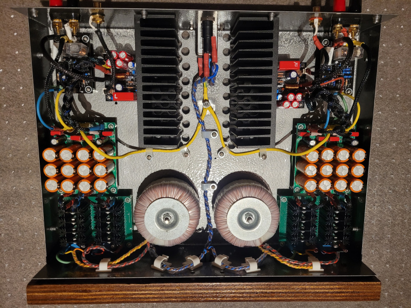 It's just been poor representation of your efforts, you deserve better, and maybe had had bad previous advice on how to upload pictures. I hope this helps (and I hope this works out, because at this editing comment point I'm just seeing text, not pictures, so I'm taking a leap of faith! ;=}) ) Best wishes;- RdM.
|
Post by RdM on May 29, 2022 21:46:21 GMT 12
Hey wow, it worked! Look at that last image upload. All your pictures could have looked like, and could have, should maybe have looked like this, or even better and bigger! That's what we want to see! ;=}) ! RdM
PS:
See if you can figure out how to follow, do that, in future.
But hey, as a project, it might be possible to go back in to the past, replace earlier images.
Maybe we're getting into science speculative fiction territory here?
Nay, you could change all the old photos or not, a lot of work, why bother?
Well maybe for pride, good retrospective viewing. Why not too? Up to you! It might make this message redundant!
But anyway, now you know how to, just go forward with the new knowledge;- upload decent sized photos next time!
|
Post by sadface on May 31, 2022 9:09:18 GMT 12
Thanks for the well wishes.
I've simply been using the default image service of the forum.
I swear you used to be able to get zoom in more on the pictures when opened up, perhaps they have changed their service from what was offered before....
Next time I will do something different like you've suggested.
Now that this project is done and making noise in my main system I am playing with a relay input selector.
|


